Compliant wirebond pedestal

a technology of wire bonding and pedestal, which is applied in the direction of manufacturing tools, soldering devices, auxillary welding devices, etc., can solve the problems of low contrast ratio, unsuitable for most image display applications, and other types of wire bonding have not yet been commercially viable, so as to reduce tool set-up time and operation intervention, and avoid the introduction of debris. , the effect of reliable ground

Inactive Publication Date: 2005-04-12
TEXAS INSTR INC
View PDF10 Cites 16 Cited by
  • Summary
  • Abstract
  • Description
  • Claims
  • Application Information

AI Technical Summary

Benefits of technology

The disclosed invention provides the technical advantage of providing a reliable ground while avoiding the introduction of debris that can harm debris-intolerant devices. The reliable ground is necessary to avoid false errors from the bond wire test process. The disclosed pedestal can be used with a variety of packages reducing tool set-up time and operation intervention.

Problems solved by technology

While some micromechanical devices, such as pressure sensors, flow sensors, and DMDs have found commercial success, other types have not yet been commercially viable.
Schlieren systems enabled the membrane devices to form images, but the images formed were very dim and had low contrast ratios, making them unsuitable for most image display applications.
This single metal layer tended to deform over a large region, however, which scattered light impinging on the deformed portion.
Micromirror devices have proven very difficult to manufacture.
Not only are the steps of forming the mirrors difficult to perform in a production environment, the completed device is extremely sensitive to debris generated by the production process.
While most semiconductor devices can be washed to remove debris and contaminants, the surface tension of a liquid used to wash the micromirror device destroys the mirror array.
One process that causes failures is the package bond out process.
While the clamp established and maintained a good ground between the wire bonder and the device package, it also generated debris particles from contact between the package and the clamp.
Since the contact was on the top of the package near the device, the particles generated could easily contaminate the mirror array.

Method used


Image

  • Compliant wirebond pedestal
  • Compliant wirebond pedestal
  • Compliant wirebond pedestal

Examples


Embodiment Construction

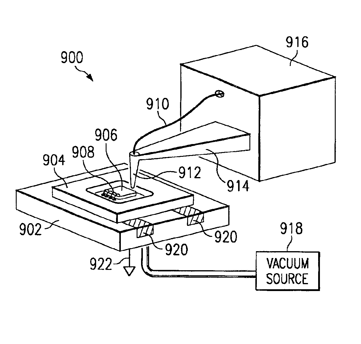
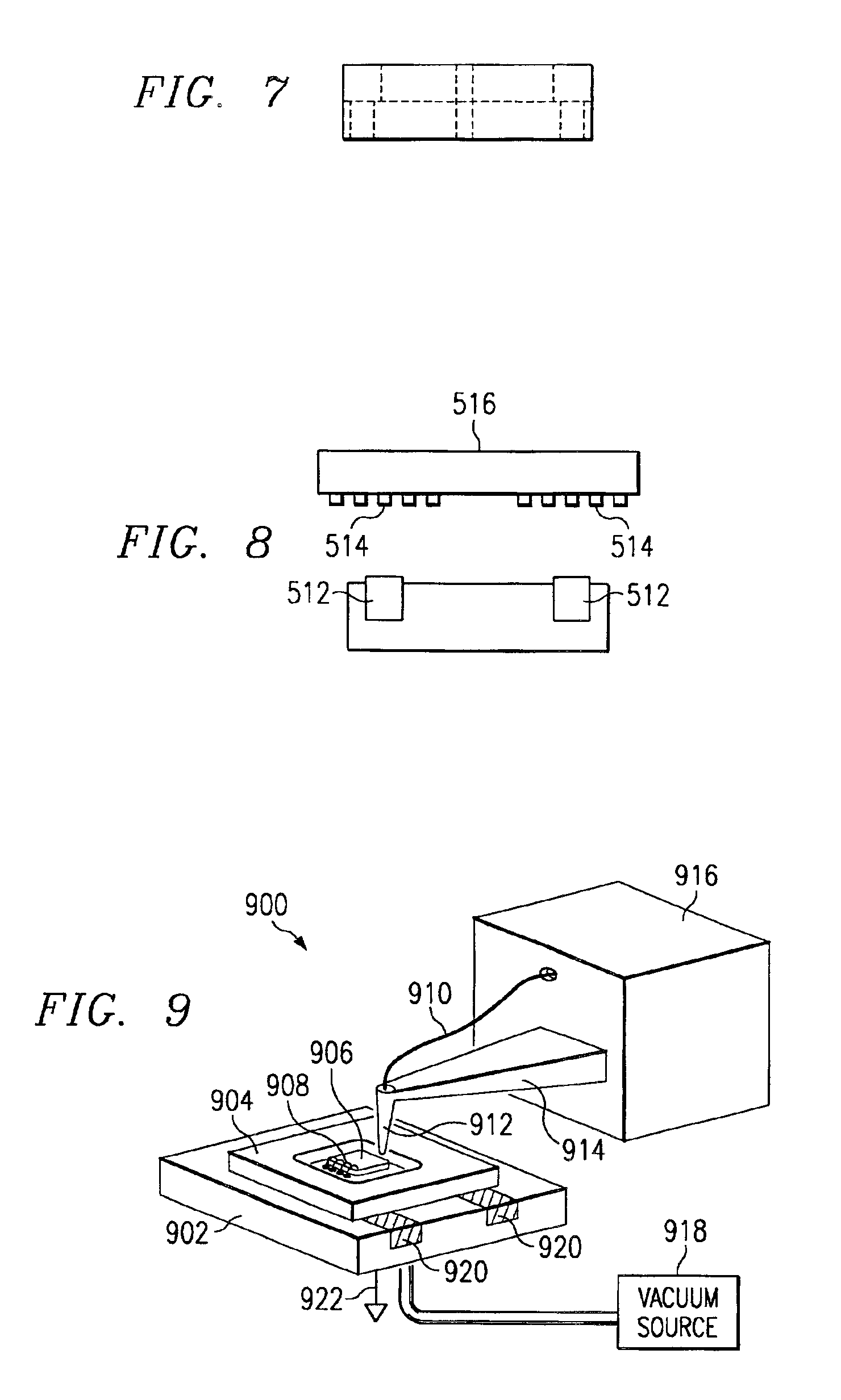
A new holding mechanism has been developed that establishes a firm attachment between a package being bonded and the wirebond machine. The mechanism relies on a conductive resilient material to make electrical contact with ground stations on the package. The resilient material is ideally coupled with a rigid pedestal to hold the resilient material and prevent excessive deformation of the resilient material or movement of the package being bonded. A vacuum cavity and port is typically provided in the pedestal to allow a vacuum to hold the device against the resilient material and pedestal.

FIG. 9 is a schematic view of a wire bonder 900 using the pedestal 902 provided by the present invention. A package 904 placed on the pedestal 902 contains an electrical device 906. The bond pads on the electrical device 906 are electrically connected to bond pads on the package 904 by a series of bond wires 908. Each bond wire 908 is attached to the bond pads through a process well known in the sem...


PUM

PropertyMeasurementUnit
vacuumaaaaaaaaaa
conductiveaaaaaaaaaa
conductive resilientaaaaaaaaaa

Abstract

A wire bonder (900) with a rigid pedestal (902) having resilient inserts (920). A package (904) placed on the pedestal (902) contains an electrical device (906). The bond pads on the electrical device (906) are electrically connected to bond pads on the package (904) by a series of bond wires (908) through use of a well know bonding process. A vacuum source holds the package (904) against the pedestal (902) deforming the resilient strips (920) located in the rigid member (902) of the pedestal and ensuring good contact between the ground pads of the package (904) and conductive resilient members (920). The resilient members (920) are conductive and electrically connect the package grounds to a system ground (922).

Description

FIELD OF THE INVENTIONThis invention relates to the field of semiconductor manufacturing, particular to semiconductor packaging, more particularly to the process of attaching bond wires between a package and a semiconductor device that is sensitive to particles generated by the bond out process.BACKGROUND OF THE INVENTIONMicromechanical devices are small structures typically fabricated on a semiconductor wafer using techniques such as optical lithography, doping, metal sputtering, oxide deposition, and plasma etching which have been developed for the fabrication of integrated circuits.A digital micromirror device (DMD™), sometimes referred to as a deformable micromirror device, is a type of micromechanical device. Other types of micromechanical devices include accelerometers, pressure and flow sensors, gears and motors. While some micromechanical devices, such as pressure sensors, flow sensors, and DMDs have found commercial success, other types have not yet been commercially viable...

Claims


Application Information

Patent Timeline
Patent Type & Authority Patents(United States)
IPC IPC(8): H01L21/00H01L21/68H01L21/67H01L21/607H01L21/02H01L21/60
CPCB23K20/004H01L21/6835H01L24/78H01L24/85Y10T29/53174H01L24/45H01L2224/45144H01L2224/78301H01L2224/78743H01L2224/85001H01L2224/85205H01L2924/01013H01L2924/01014H01L2924/01029H01L2924/01047H01L2924/01079H01L2924/01082H01L2924/01327H01L2924/14H01L2924/3011B23K2201/40Y10S228/904Y10S269/903H01L2924/01033H01L2924/00014H01L2224/48H01L2924/00B23K2101/40H01L2224/45099H01L2924/00015
Inventor MARSH, JEFFREY W.WHITE, R. TRACYHAMILTON, DAVID L.
Owner TEXAS INSTR INC
Why Eureka
Try Eureka