
High altitude stripping for threat discrimination

a technology of threat discrimination and high altitude stripping, applied in the field of missile interceptors, to achieve the effect of improving spatial resolution

Inactive Publication Date: 2005-04-12
BAE SYST INFORMATION & ELECTRONICS SYST INTERGRATION INC
View PDF16 Cites 51 Cited by
  • Summary
  • Abstract
  • Description
  • Claims
  • Application Information

AI Technical Summary

Benefits of technology

The present invention is a method of discriminating between threat objects and decoy objects at high altitudes where it was thought stripping would be to no avail. Stripping is in fact made possible by providing a dual mode IR and LADAR seeker on a kill vehicle which analyses various target characteristics when the kill vehicle is within range. On board computers use these characteristics to discriminate a threat target from decoys and direct the kill vehicle to the target. First a dual mode IR and LADAR seeker is used to obtain precise target dynamic measurements of the objects. Atmospheric drag is then determined from these measurements to separate the objects into threat objects and decoy objects. After this determination, the track to the threat object is calculated and the kill vehicle is directed to intercept the identified threat. The subject system permits primary target complex acquisition and tracking using a two color cryo-cooled passive IR / direct-detect LADAR dual-mode seeker which is deployed after launch and enables target filtering to reduce the number of credible threats. Target cloud acquisition is at 1,000 km, with target acquisition at 500 km and LADAR acquisition at 350 km in one embodiment. Fast scan technology is used along with a common aperture design for the IR and LADAR sensors. The result is improved separation of closely spaced objects and the support of multi-color IR threat classification to improve kill ratios.
Note that the LADAR improves the spatial resolution by a factor of 5 over a typical missile defense MWIR seeker using a common aperture. The LADAR also provides a 3D angle, angle, range (AAR) image for each laser pulse which is used to extract the precise target state vectors.

Problems solved by technology

This coupled with a cluttered battle space which includes booster debris, previous intercepts and raid attacks, results in a situation in which there are numerous closely spaced objects, CSOs.

Method used


Image

  • High altitude stripping for threat discrimination
  • High altitude stripping for threat discrimination
  • High altitude stripping for threat discrimination

Examples


Embodiment Construction

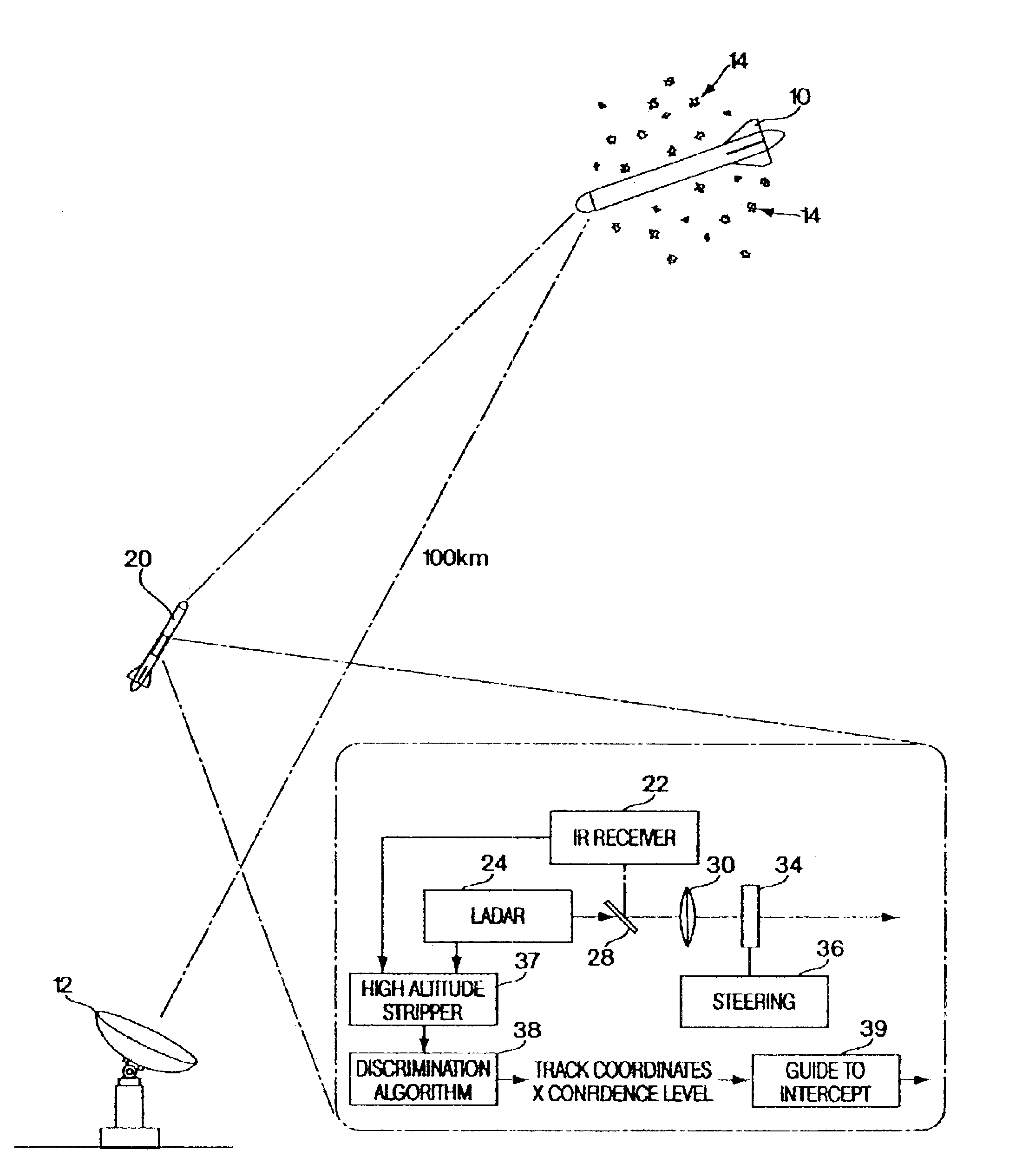
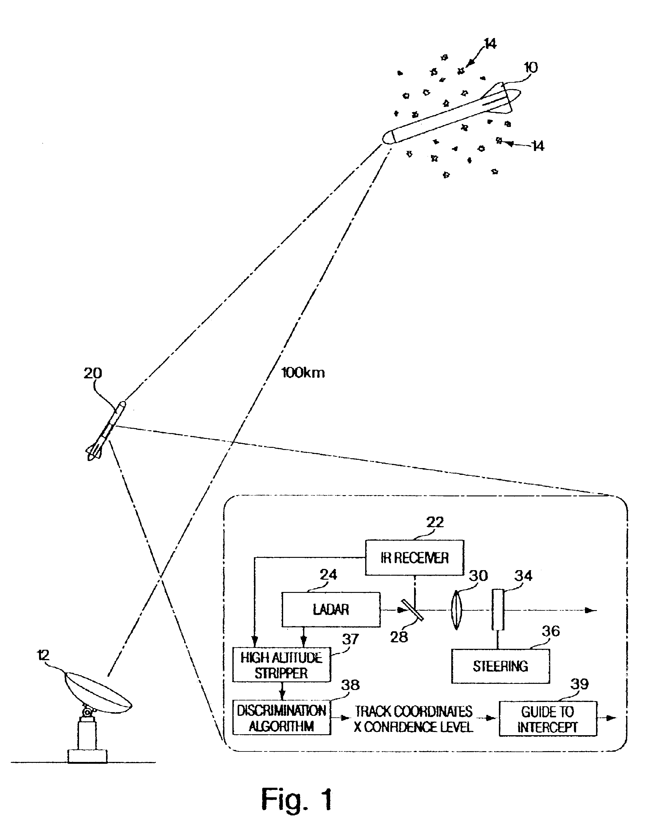
Referring now to FIG. 1, in a tactical situation a reentry vehicle 10 is detected by ground based radar 12 which provides an initial track for the reentry vehicle along with decoys 14 which may include spherical or conical decoys or chaff used to confuse a kill vehicle 20 which is launched upon detection of the reentry vehicle.

On board reentry vehicle 20 is a dual-mode detector which includes an IR receiver 22 and LADAR unit 24 with the receiver and the LADAR unit having a common optical axis 26 including beam splitter means 28 optics 30, a steering mirror 34 and a steering control unit 36.

The output of the IR receiver and the LADAR unit are coupled to a high altitude stripper 37 which is in turn coupled to a discrimination algorithm 38 for outputting the track coordinates along with a confidence level for all the objects detected by the IR receiver and the LADAR system. The track coordinates along with the confidence level are utilized by an intercept computer 39 to guide the kill ...


PUM


Abstract

A technique is provided that uses a dual mode seeker (IR and LADAR) for precise target dynamics measurement, which extends stripping to a much higher altitude than ground based radar. Initial results show that this approach works to altitudes in excess of 100 km. Stripping becomes a reliable way to discriminate lighter weight decoys from reentry vehicles at altitudes and ranges consistent with planned divert capabilities for terminal phase missile defense. It is a finding of this invention that the LADAR will improve the spatial resolution by a factor of five over typical missile defense IR seekers using a common aperture. The LADAR provides a 3D angle, angle, range (AAR) image for each laser pulse which is used to extract the precise target state vectors.

Description

FIELD OF INVENTIONThe present invention relates to missile interceptors and more particularly to means for discriminating between threats and decoys.BACKGROUND OF THE INVENTIONOne of the most difficult technical challenges for Hit-to-Kill Missile Defense Systems is target discrimination. Nations that have a technology base to produce missiles and warheads will be capable of some level of countermeasures. Also launch and deployment debris contribute many objects to the threat cloud.In current missile defense systems the bulk of this discrimination task falls on surface based radar supported by overhead assets. The primary radar discrimination methods are dependent on object trajectory and dynamics. The addition of an angle, angle, range (AAR) laser radar or LADAR to an IR seeker brings a number of possibilities for discrimination, robust tracking in the presence of countermeasures and clutter, accurate aim point selection and others including the use of high resolution tracks of unre...

Claims


Application Information

Patent Timeline
Patent Type & Authority Patents(United States)
IPC IPC(8): G01S7/48G01S7/495G01S7/02G01S7/36G01S7/41
CPCG01S7/495G01S7/4802G01S7/36G01S7/414G01S7/415
Inventor DEFLUMERE, MICHAEL E.BULPETT, MICHAEL P.BOYD, TIMOTHY J.NORDHAUS, KURT J.
Owner BAE SYST INFORMATION & ELECTRONICS SYST INTERGRATION INC
Learn More