Helical electron beam generating device and method of use

a helical electron beam and beam generating technology, applied in the field of cancer radiation treatment devices, can solve the problems of high risk of cardiac or pulmonary complications, compromising the treatment of these patients using conventional radiation therapy techniques, and excessive heart or lung volume for irradiation

Inactive Publication Date: 2005-04-12
UNIV OF MARYLAND BALTIMORE
View PDF11 Cites 33 Cited by
  • Summary
  • Abstract
  • Description
  • Claims
  • Application Information

AI Technical Summary

Problems solved by technology

However, the high risk of cardiac or pulmonary complications often compromises the treatment of these patients using conventional radiation therapy techniques.
(1) Limited beam setup options. Patient geometry may sometimes include excessive heart or lung volume for irradiation.
(2) Unable to treat internal mammary nodes because of the proximity of the node chains to the heart.
(3) Potential high scatter dose to the contralateral breast.
(4) Patient breathing motion may introduce accidental irradiation of large volume of heart or lung.
These restrictions especially the first one have restricted the use of photon beam radiation therapy for advanced breast cancer treatment.
Several clinical studies have reported significant rate of cardiac or pulmonary toxicity associated with the conventional photon beam techniques [17-27].
The limitation of photon beam breast treatment is evident from a recent study that compares the photon Intensity Modulation Radiotherapy (IMRT) technique with the conventional radiation therapy techniques for breast cancer treatment [28].
This result implies that there may be not much room in improving the existing techniques for photon beam treatment of breast cancers.
Second, the electron beam exhibits fast fall-off near the end of its range of travel.
Because the anterior-posterior direction of the breathing motion coincides with the beam-on direction, the simple treatment setup reduces the possibility of over irradiation of the heart or lung due to patient breathing motion.
One major disadvantage of electron beams is their excessive scatter and beam penumbra.
But the problem with electron beams is their tendency to scatter.
This approach requires significant modification of the design for most clinical linear accelerators; and thus is not feasible.
This approach has not yet solved the problem the excessive electron beam scatter effects.
None of these studies and experiments has proven to be successful yet.

Method used


Image

  • Helical electron beam generating device and method of use
  • Helical electron beam generating device and method of use
  • Helical electron beam generating device and method of use

Examples


Embodiment Construction

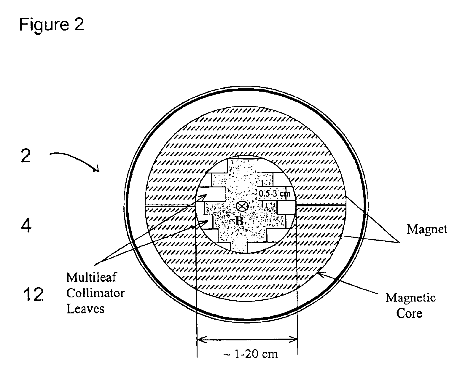
Static magnetic fields can shape the electron paths. Under an axial magnetic field, any scatter or divergent electrons can be constrained to follow helical trajectories. The simulation of electron beam trajectories under an axial magnetic field indicates electrons traveling in a helical path. Electrons under an axial magnetic field have a much sharper penumbra and improved range straggling. However, strong magnetic fields about 3-6 Telsa are needed to generate a useful helical electron beam with gyration radius of 1-2 mm [59]. Such strong magnetic fields require bulky and expensive super-conducting magnets.

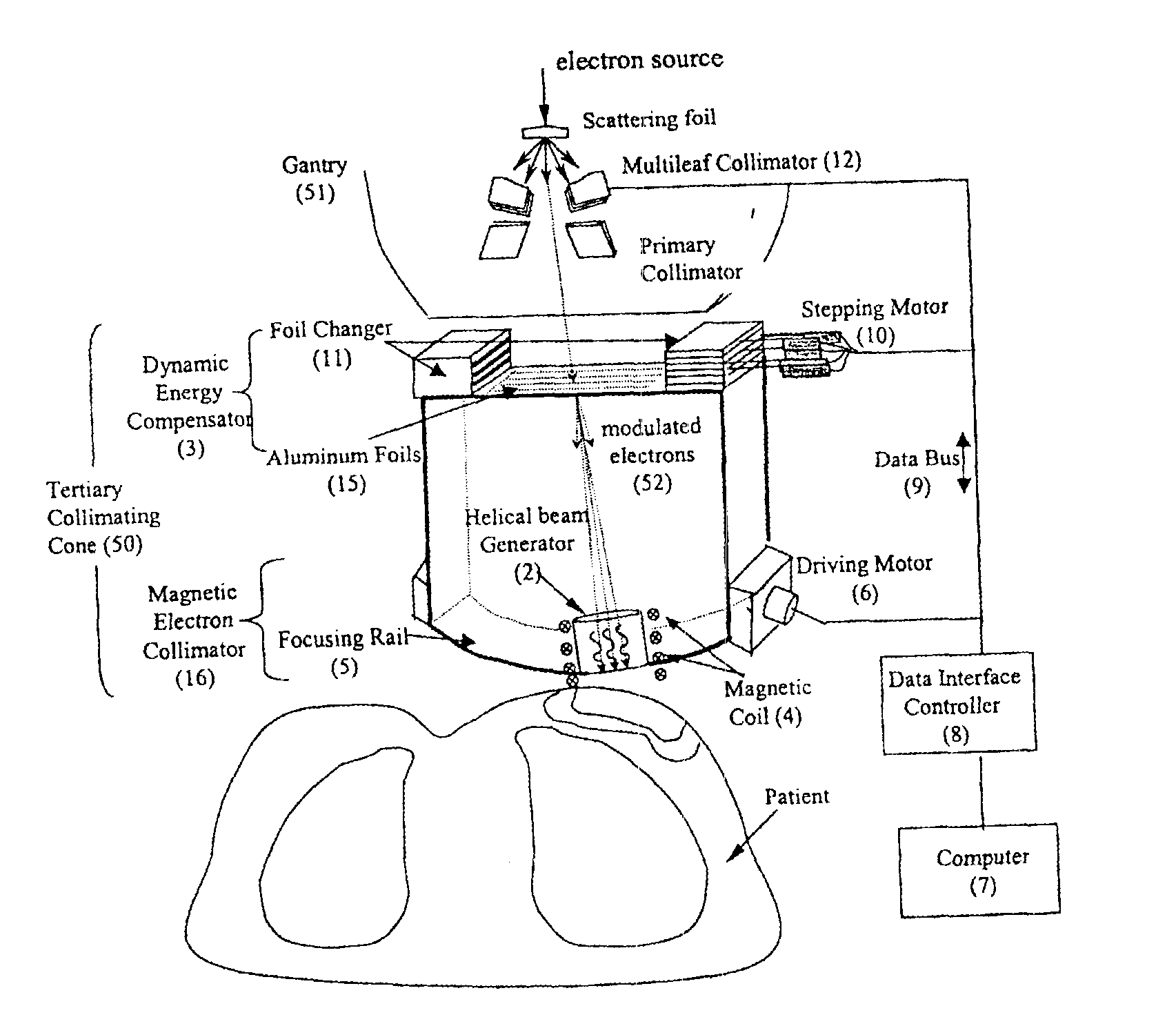
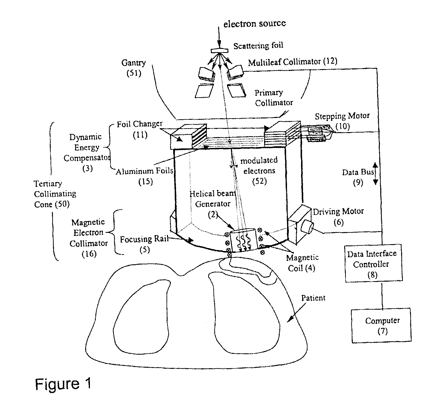
As shown in FIG. 1, the preferred embodiment of this invention uses a tertiary collimating cone, 50, having a magnetic electron collimator, 16, and a dynamic energy compensator, 3, to generate a modulated electron beam that travels in a helical path. The magnetic electron collimator contains a helical beam generator, 2, which uses a magnetic coil, 4, that produces a magnetic field...


PUM


Abstract

A device for generating helical electron beams that can be used for radiation therapy is disclosed. The device contains a tertiary collimating cone that can be attached to a gantry of a linear accelerator or placed directly below the gantry. The tertiary collimating cone has a dynamic energy compensator and a magnetic electron collimator to modify the energy of electrons and to generate a helical trajectory. A multileaf collimator may be present within the tertiary collimating cone. A computer coordinates the movements of various components. The helical electron beam produced by this device can be targeted to tumors better and safer and reduce the amount of radiation hitting normal tissue than current devices.

Description

BACKGROUND OF THE INVENTION1. Field of InventionThis invention relates to a device for radiation treatment for cancer and the method thereof. It more specifically relates to a device to generate helical electron beams for radiation therapy for tumors and the method of irradiating tumors with a helical electron beam.2. Description of the Related ArtRadiation therapy has been effective for managing early stage (stage I-II) breast cancers following breast conservation surgery (BCS). More recent studies have indicated that radiation therapy also improves survival rate for late stage (stage III-IV) breast cancer patients. However, the high risk of cardiac or pulmonary complications often compromises the treatment of these patients using conventional radiation therapy techniques.Conventional photon beams have been used successfully for treating early stage breast cancer treatment. It is now widely accepted that radiation therapy following breast conservation therapy is as effective as mas...

Claims


Application Information

Patent Timeline
Patent Type & Authority Patents(United States)
IPC IPC(8): A61N5/10H01S3/0955H01S3/0959
CPCA61N5/1042H01S3/0959A61N2005/1089A61N5/1043
Inventor MA, LIJUN
Owner UNIV OF MARYLAND BALTIMORE
Why Eureka
Try Eureka