Configuration and method for manufacturing compact high current inductor coil

a high-current inductor coil and configuration technology, which is applied in the direction of coils, basic electric elements, inductances, etc., can solve the problems of increasing production costs, complicating manufacturing processes, and insufficient compact form factor of current inductor coils, etc., to achieve improved form factors, simplified manufacturing processes, and reduced production costs

Active Publication Date: 2005-04-12
CYNTEC
View PDF4 Cites 26 Cited by
  • Summary
  • Abstract
  • Description
  • Claims
  • Application Information

AI Technical Summary

Benefits of technology

It is therefore an object of the present invention to provide a new structural configuration and manufacture method for manufacturing an inductor with simplified manufacturing processes to produce inductors with improved form factors having smaller height and size and more device reliability.

Problems solved by technology

For those of ordinary skill in the art, the configurations and the process of manufacturing a high current inductor coil are still faced with technical challenges that inductor coils manufactured with current technology still does not provide sufficient compact form factor often required by application in modern electronic devices.
Furthermore, conventional inductor coils are is still manufactured with complicate manufacturing processes that involve multiple steps of epoxy bonding and wire welding processes.
The production cost is also increased due to the requirements that the lead frame and the coil must be separately manufactured.
The manufacture processes are further complicated as several welding and bonding steps are required to securely attach the welding ends of the flat wire to the welding points of the lead frame.
The production yields and time required to manufacture the inductor coil are adversely affected due to the more complicate inductor configurations and multiple boding and welding manufacturing processes.

Method used


Image

  • Configuration and method for manufacturing compact high current inductor coil
  • Configuration and method for manufacturing compact high current inductor coil
  • Configuration and method for manufacturing compact high current inductor coil

Examples


Embodiment Construction

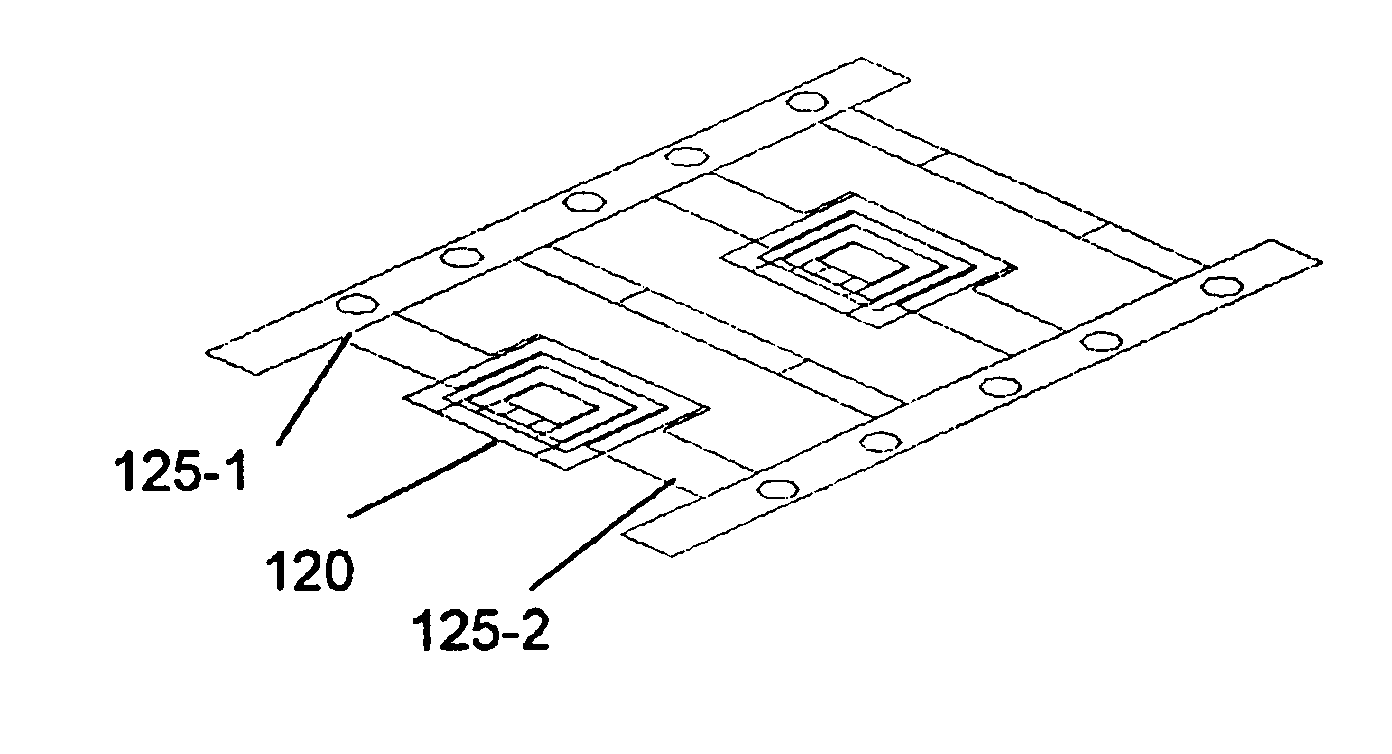
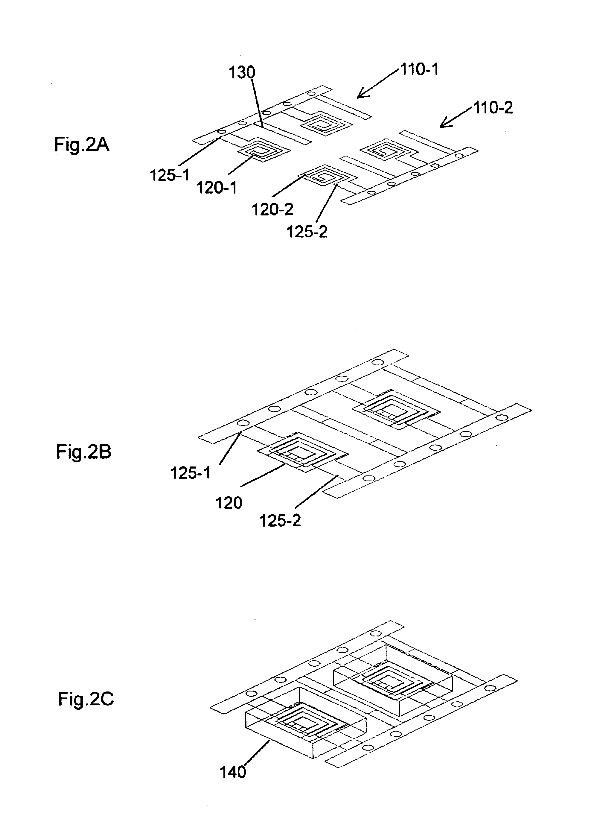
Referring to FIGS. 2A to 2E for a series of perspective views to illustrate the manufacturing processes of this invention. In FIG. 2A, a first and a second conductive plates 110-1 and 110-2 are press punched into a first coil layer 120-1 integrated with a first lead 125-1 and a second coil layer 120-2 integrated with a second lead 125-2 each having a conductive lead 130. A preferred conductive plate may be a copper plate for press punching into the first and second conductive layers 110-1 and 110-2. The copper layer may be enameled copper with a polymide enamel coating for insulation. More details of the conductive material for making the inductor coil layer 220-1 and 220-2 may be referred to U.S. Pat. No. 6,204,744. In FIG. 2B, the first and second coil layers 120-1 and 120-2 and also the leads 130 are overlapped and welded together thus the first coil layer 120-1 and the second coil layer 120-2 are connected as a inductor coil 120. The inductor coil 220 and the leads 125-1 and 125...


PUM

PropertyMeasurementUnit
conductiveaaaaaaaaaa
shapeaaaaaaaaaa
magneticaaaaaaaaaa

Abstract

This invention discloses a method for manufacturing an inductor by first press punching a first and a second layer of conductive plates into a first and second coil layers with a first and second inductor lead layers as single integrated layers. The manufacturing process further includes a step of overlapping and connecting the first and second coil layers to form an inductor. In a preferred embodiment, process of manufacturing further includes a step of mixing epoxy to bond with a highly magnetic material and pressure molding the bonding magnetic material around the coil layers to form an inductor.

Description

BACKGROUND OF THE INVENTION1. Field of the InventionThis invention relates generally to the device configuration and processes for manufacturing inductor coils. More particularly, this invention relates to an improved configuration and process for manufacturing compact and high current inductor coils.2. Description of the Prior ArtFor those of ordinary skill in the art, the configurations and the process of manufacturing a high current inductor coil are still faced with technical challenges that inductor coils manufactured with current technology still does not provide sufficient compact form factor often required by application in modern electronic devices. Furthermore, conventional inductor coils are is still manufactured with complicate manufacturing processes that involve multiple steps of epoxy bonding and wire welding processes.Shafer et al. disclose a high current low profile inductor in a U.S. Pat. No. 6,204,744, as that shown in FIG. 1. The inductor disclosed by Shafer et a...

Claims


Application Information

Patent Timeline
Patent Type & Authority Patents(United States)
IPC IPC(8): H01F27/29H01F27/02
CPCH01F27/027H01F27/292H01F2017/048H01F2017/046
Inventor LIU, CHUN-TIAOHUANG, YI-MIN
Owner CYNTEC
Why Eureka
Try Eureka