System and method for programmable polarization-independent phase compensation of optical signals

a phase compensation and optical signal technology, applied in the field of optical communication and the processing of optical signals, to achieve the effect of reducing, adjusting or otherwise adjusting the chromatic dispersion of optical signals

Inactive Publication Date: 2005-04-12
PURDUE RES FOUND INC
View PDF2 Cites 45 Cited by
  • Summary
  • Abstract
  • Description
  • Claims
  • Application Information

AI Technical Summary

Benefits of technology

The present invention relates to optical communications and the processing of optical signals, and in particular relates to systems and methods for adjusting the phase of optical signals having an arbitrary polarization. The present invention finds particularly utility in correcting, reducing or otherwise adjusting chromatic dispersion in optical signals.

Problems solved by technology

This capability allows optical fiber lightwave communication systems to run at higher speeds over longer distances by compensating chromatic dispersion, which is regarded as a key impairment for high-performance lightwave communication systems.

Method used


Image

  • System and method for programmable polarization-independent phase compensation of optical signals
  • System and method for programmable polarization-independent phase compensation of optical signals
  • System and method for programmable polarization-independent phase compensation of optical signals

Examples


example embodiments

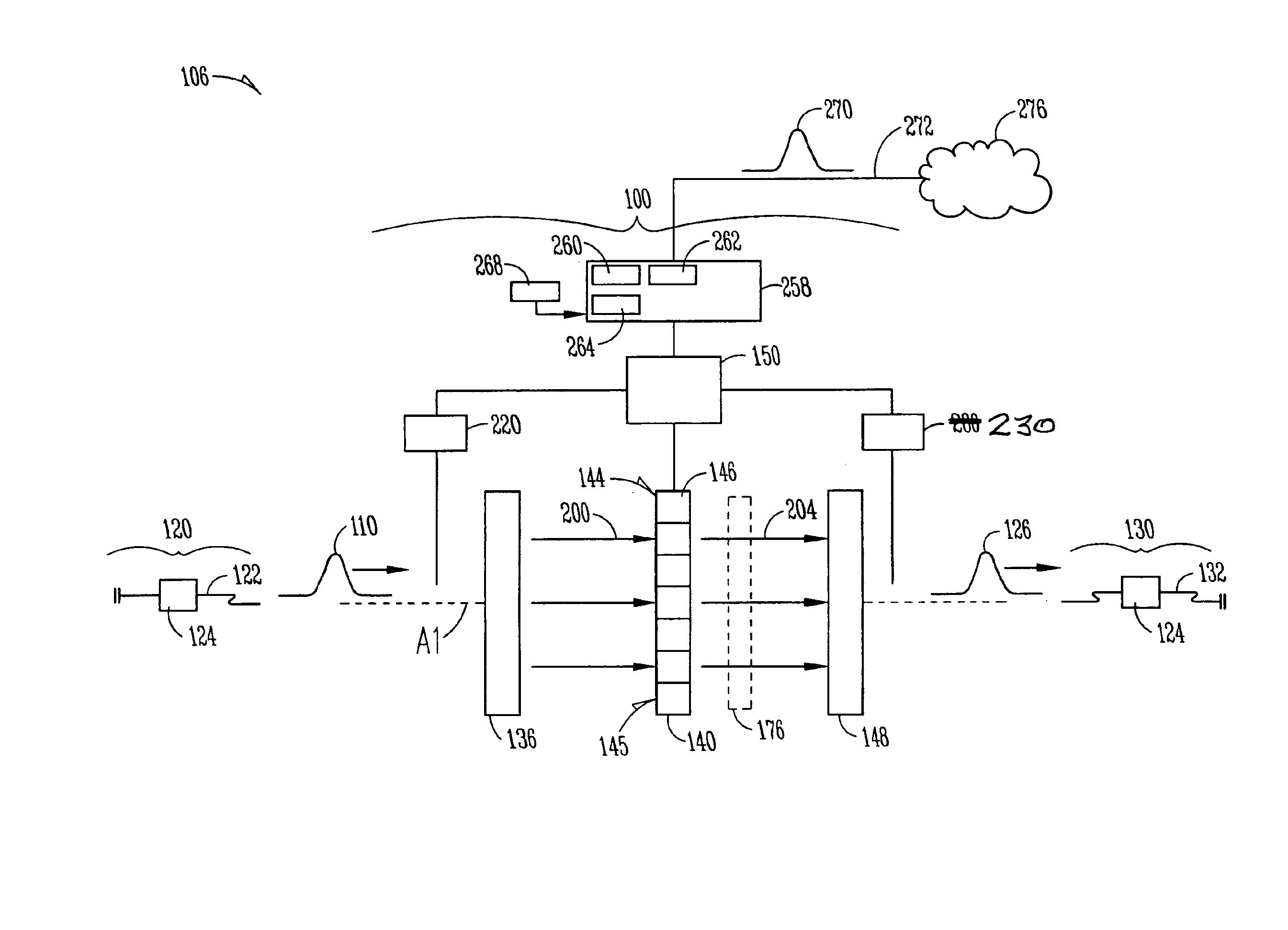
As mentioned above, there are many specific examples of system 100 of FIG. 1. Several of these examples are described below for the sake of illustration, and one skilled in the art will appreciate that the examples provided in no way limit the general teaching of the chromatic dispersion compensation system of the present invention.

Transmission System with Liquid Crystal PI-SLM and Diffraction Gratings

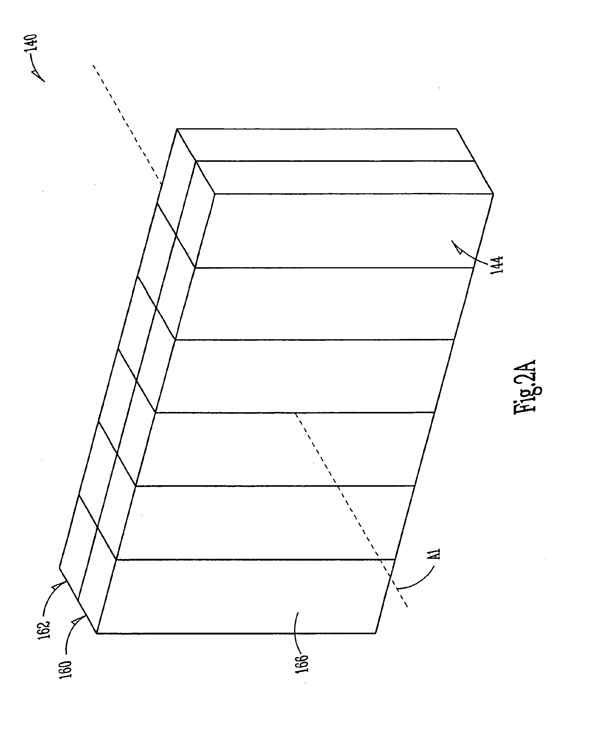
Referring now to FIG. 3, a first exemplary embodiment of system 100 is shown. In this embodiment, first dispersive module 136 includes a first grating 300 for receiving optical signal 110 and angularly dispersing its frequency components 200, and a first lens 306 having a focal length F1 for collimating the angularly dispersed frequency components and focusing them onto a liquid-crystal-based PI-SLM 140, and in particular onto first and second arrays 160 and 162 of elements 166 (FIG. 2A).

Optical signal 110 emanates from the end of an output optical fiber 122 as part of optical system 1...


PUM

PropertyMeasurementUnit
phaseaaaaaaaaaa
frequencyaaaaaaaaaa
chromatic dispersionaaaaaaaaaa

Abstract

A system and method for programmable phase compensation of optical signals is disclosed. The systems and methods include the use of a polarization-independent spatial light modulator (PI-SLM), so that the state of polarization (SOP) of the incoming optical signal need not be known. The system includes a first dispersive module that spatially separates the optical signal into its frequency components. The frequency components are spread over the active area of the PI-SLM. The active area of the PI-SLM includes an array of independently programmable addressable regions capable of altering the phase of the light incident thereon. An exemplary application of the invention is chromatic dispersion compensation. By knowing the amount of chromatic dispersion in the optical signal, or alternatively, by knowing the amount of chromatic dispersion to be introduced into the optical signal downstream, the appropriate phase adjustments can be made to each frequency component of the signal. The phase-adjusted frequency components are then recombined via a second dispersive module to form a compensated optical signal.

Description

FIELD OF THE INVENTIONThe present invention relates to optical communications and the processing of optical signals, and in particular relates to systems and methods for adjusting the phase of optical signals having an arbitrary polarization.BACKGROUND OF THE INVENTIONThe transmission of information over optical fibers is becoming pervasive. This is motivated, at least in part, because optical fiber offers much larger bandwidths than electrical cable. Moreover, optical fiber can connect nodes over large distances and transmit optical information between such nodes at the speed of light.There are, however, a number of physical effects that limit the ability to transmit large amounts of information over an optical fiber. One such effect is called “chromatic dispersion,” which refers to the spreading of a pulse of light (i.e., an “optical signal” or “lightwave signal”) due to the variation in the propagation velocity of the different optical frequencies (or equivalently, wavelengths) m...

Claims


Application Information

Patent Timeline
Patent Type & Authority Patents(United States)
IPC IPC(8): H04B10/18G02F1/1347
CPCG02F1/13471H04B10/2513G02F2201/17G02F2203/50G02F2203/12
Inventor WEINER, ANDREW MARC
Owner PURDUE RES FOUND INC
Why Eureka
Try Eureka