Valve device

a valve and valve seat technology, applied in the direction of valve release devices, valve operating means/release devices, mechanical equipment, etc., can solve the problems of increase the cost of valve seat plates, and difficult to obtain precise dimensions and positions of holes, etc., to achieve excellent planarity and prevent the effect of changing the planarity

Active Publication Date: 2005-04-19
SANKYO SEIKI MFG CO LTD
View PDF3 Cites 21 Cited by
  • Summary
  • Abstract
  • Description
  • Claims
  • Application Information

AI Technical Summary

Benefits of technology

[0015]In this present invention, it is preferable that the first plate member have a large diameter portion on the back surface side of the valve seat plate, and the first plate member and the second plate member be joined together by brazing from the back surface side. This configuration can prevent the surface precision of the valve seat plate, on which the valve element rotates, from being degraded due to the brazing material.
[0016]In the present invention, it is preferable that the thickness of the first plate member be 2.1 mm or more, and more suitably 2.4 mm or more. When the outlet pipes are first inserted into the pipe-inserting holes in th

Problems solved by technology

For these reasons, when the valve seat plate 13′ is manufactured conventionally, a thick SUS needs to be lathed, which increases the cost of the valve seat plate 13′.
Although forging may be considered in place of lathing, as a manufacturing method for a valve seat plate, it is also an expensive method though not as costly as lathing.
Also, it is difficult to obtain precise dimensions and positions of the holes.
Also, forging creates a great residual stress on the surface; therefore, when

Method used


Image

  • Valve device
  • Valve device
  • Valve device

Examples


Embodiment Construction

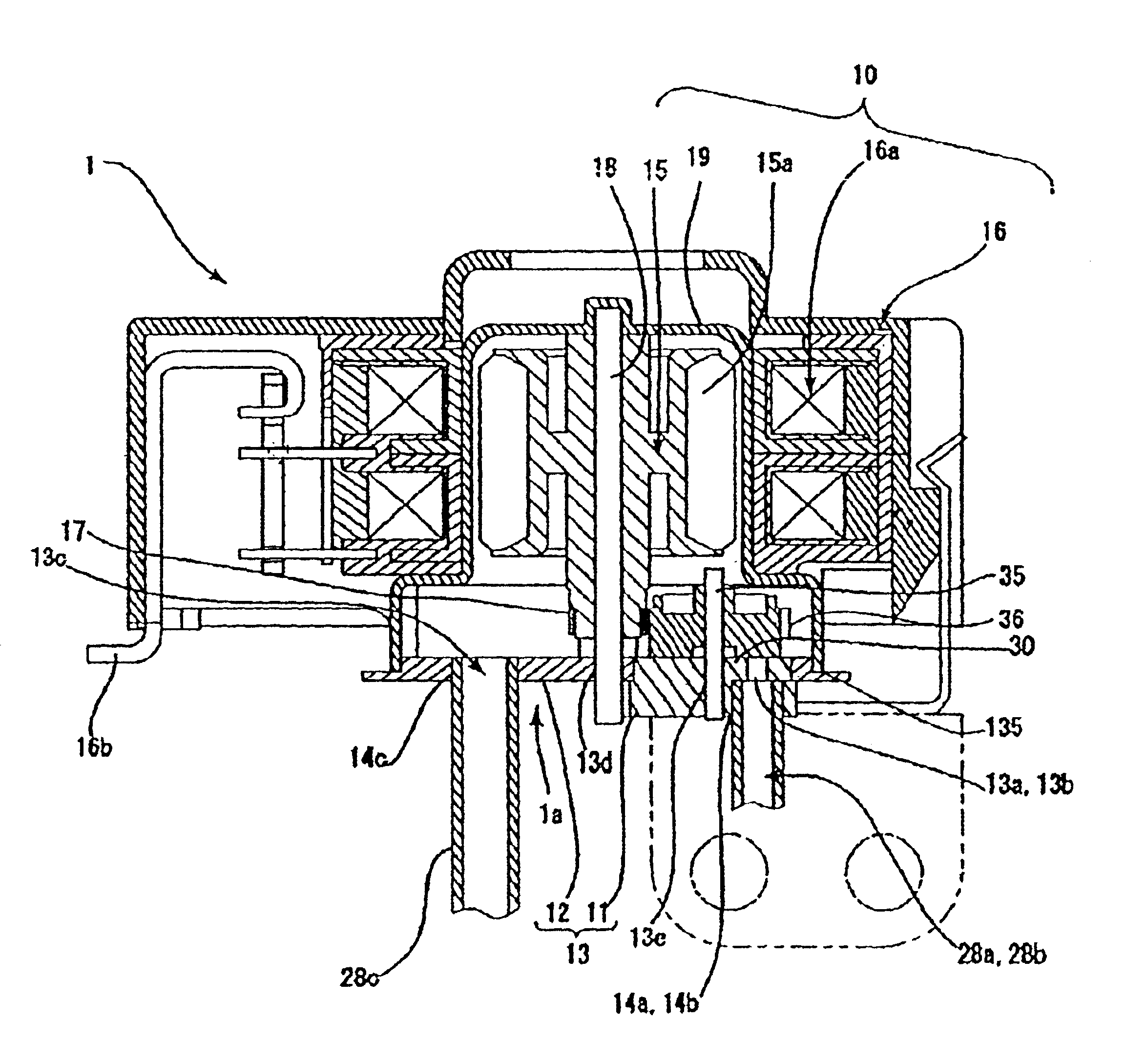
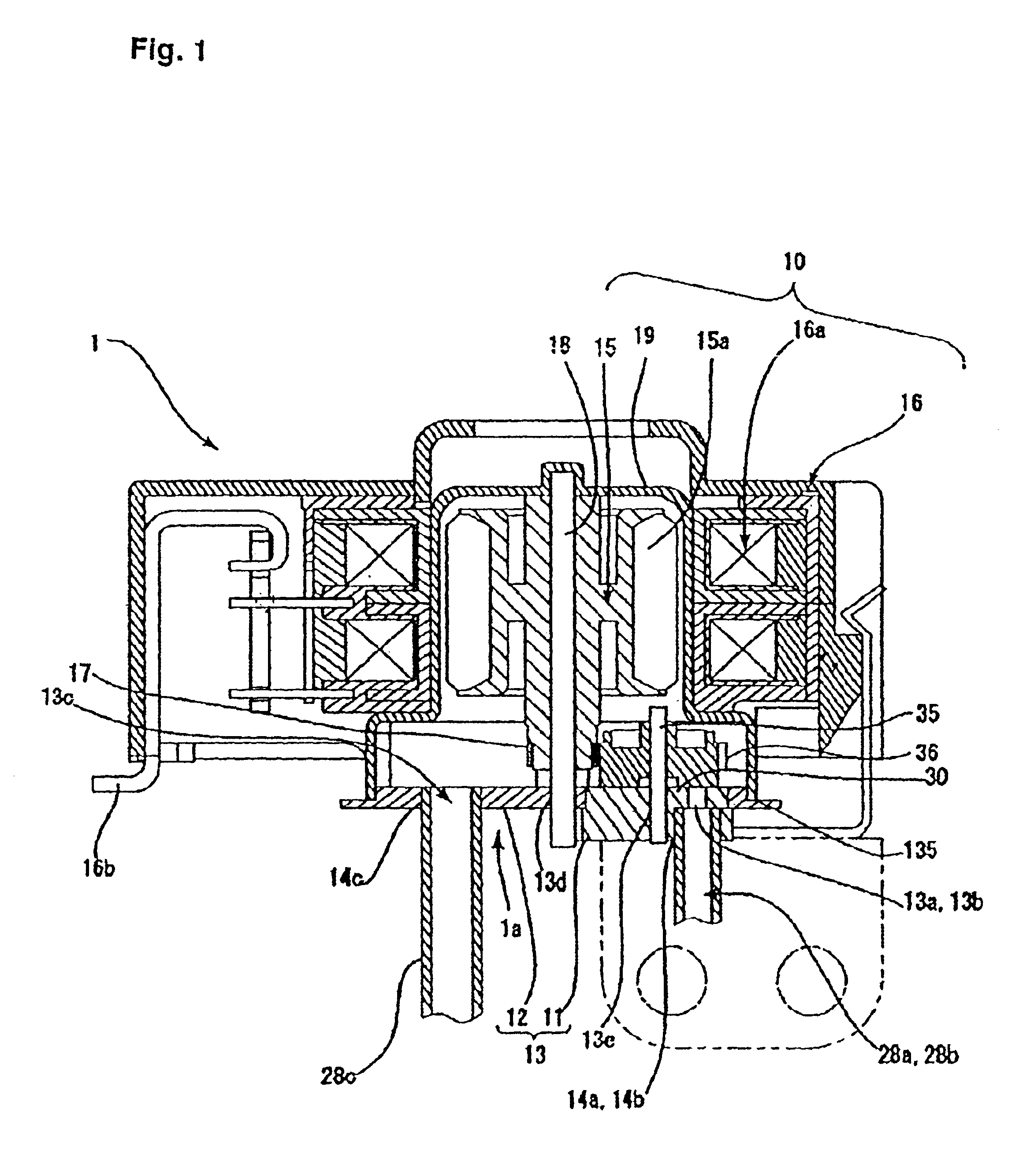
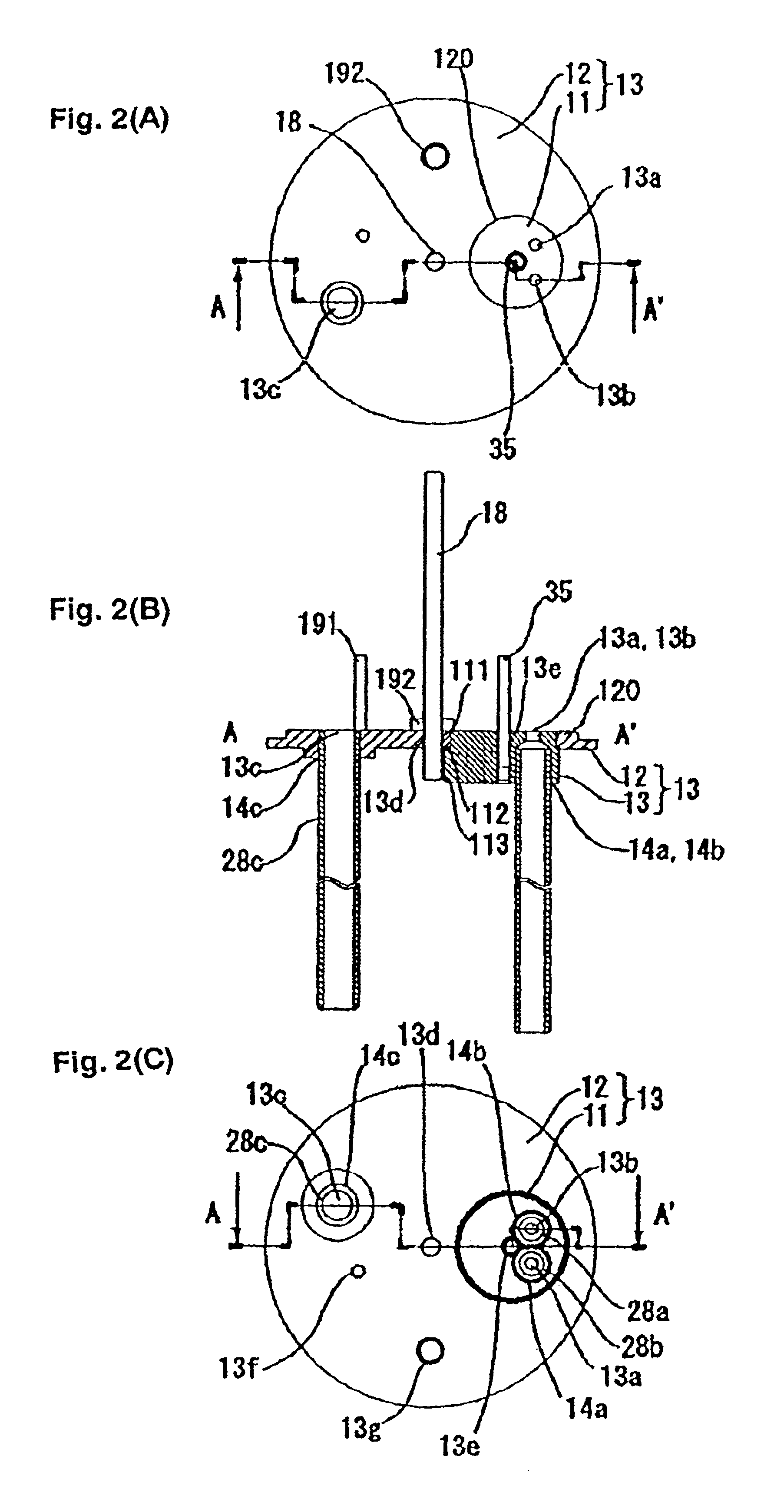
[0024]FIG. 1 is a vertical cross-sectional view of a refrigerant distribution device of a refrigerator, to which the present invention is applied. FIGS. 2(A), (B), and (C) are respectively a plan view, a vertical cross-sectional view, and a bottom view of a valve seat plate of a valve device which is used in the refrigerant distribution device illustrated in FIG. 1. FIG. 2(B) is a cross-section of the valve seat plate along the A-A′ line of FIGS. 2(A) and (C). FIGS. 3(A) through (F) are respectively diagrams for the modes of the refrigerant distribution device illustrated in FIG. 1.

[0025]In FIG. 1, a refrigerant distribution device 1 of this embodiment has a valve device 1a equipped with a valve seat plate 13 and a sealing case 19 which covers the front side of the valve seat plate.

[0026]In the valve device 1a, a stepping motor 10 is configured inside and outside of the sealing case 19 as a valve drive device to drive a valve element. In the stepping motor 10, a rotor 15 is position...


PUM


Abstract

A valve device having a novel vale seat plate is provided. The valve seat plate has an inlet opening, an outlet opening, a front side and a back side. A sealing case covers the front side and inlet and outlet pipes are attached to the back side to communicate respectively with the inlet and outlet openings. A valve element moves to cover the outlet opening on the front side to close the outlet opening. The novel valve seat plate includes at least two plates that are joined to each other. One plate forms the area around the outlet opening and the other plate forms other areas of the valve seat plate.

Description

BACKGROUND OF THE INVENTION[0001]1. Field of Invention[0002]The present invention relates to a valve device. More specifically, it relates to configuration of a valve seat plate which is used in the valve device.[0003]2. Description of Related Art[0004]In refrigerators, a valve device is used to distribute a common refrigerant (fluid) to a plurality of compartments to cool them. As illustrated in FIGS. 6(A) and (B), such a valve device comprises a valve seat plate 13′ having a refrigerant inlet opening 13c and refrigerant outlet openings 13a and 13b through which a refrigerant flows in the thickness direction, a sealing case (not illustrated) which covers a front surface of the valve seat plate 13′, and a valve element (not illustrated) which rotates on the front surface of the valve seat plate 13′ to open and close the refrigerant outlets 13a and 13b. Also, a rotor support shaft 18 and a valve element support shaft 35 are fixed to the valve seat plate 13′.[0005]In the valve seat pl...

Claims


Application Information

Patent Timeline
IPC IPC(8): F16K31/04F16K3/02F16K3/08F16K11/074
CPCF16K31/041F16K3/08Y10T137/6031F16K31/04
Inventor HARA, TETSUHIKOOZAWA, SHIGERU
Owner SANKYO SEIKI MFG CO LTD
Why Eureka
Try Eureka