Flashlight using a light emitting diode as a lamp

Inactive Publication Date: 2005-04-19
AITEC
View PDF13 Cites 68 Cited by
  • Summary
  • Abstract
  • Description
  • Claims
  • Application Information

AI Technical Summary

Benefits of technology

[0015]The present invention has been made to solve the above problems of prior arts, therefore, it is a first object of the present invention to provide an LED flashlight capable of improving directionality of light such that light

Problems solved by technology

In addition, since the LED is operated with very low power, the LED can keep longer that the filament bulb.
However, the conventional LED flashlight requires a great number of parts for connecting the electrodes and the lead wires, so an assembling process thereof is very complicated.
Intensity of current passing through high-luminance LEDs is higher than intensity of current passing through conventional LEDs, so heat is generated when using the high-luminance LEDs for a long time.
In extreme cases, the characteristic of the

Method used


Image

  • Flashlight using a light emitting diode as a lamp
  • Flashlight using a light emitting diode as a lamp
  • Flashlight using a light emitting diode as a lamp

Examples


embodiment 1

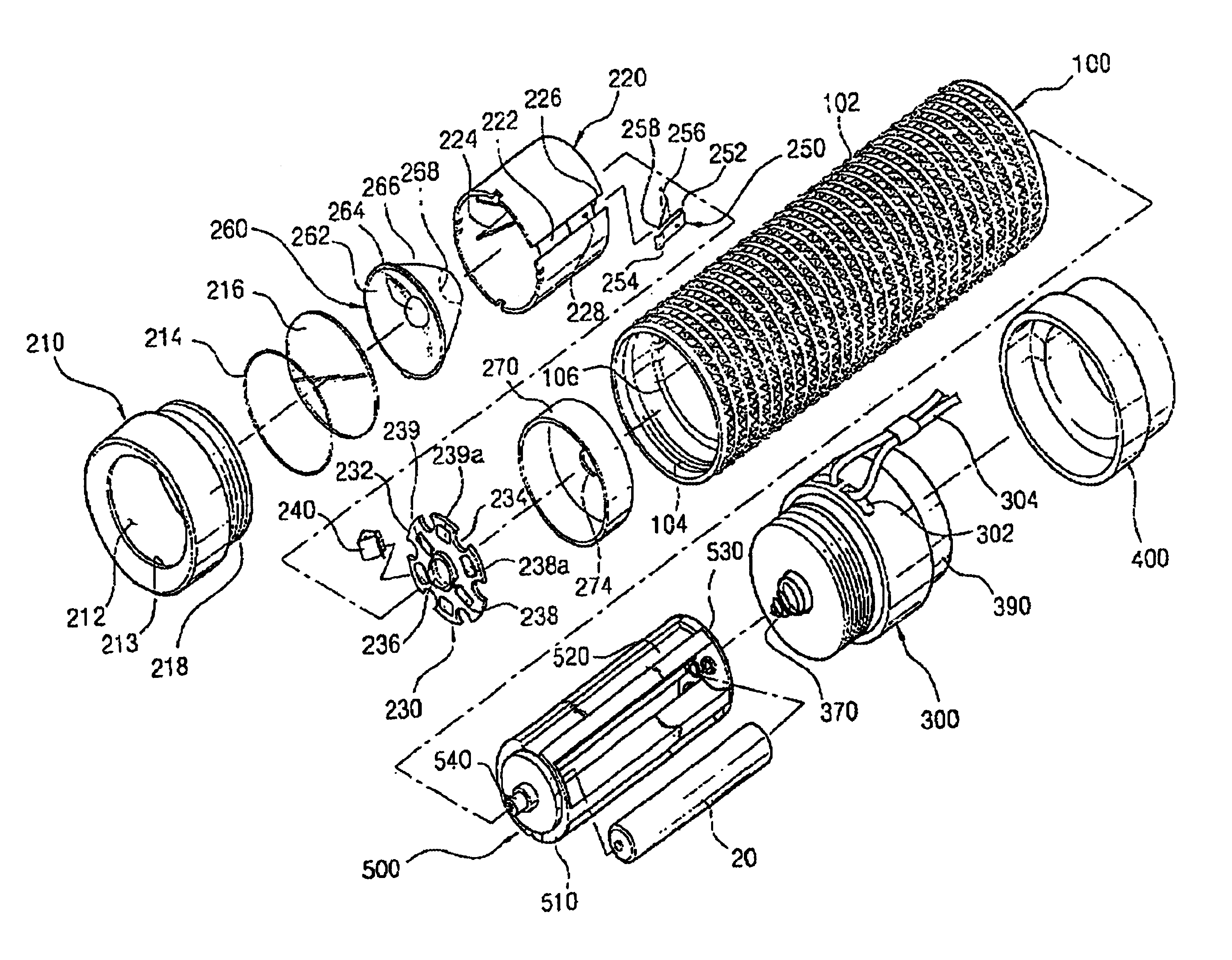
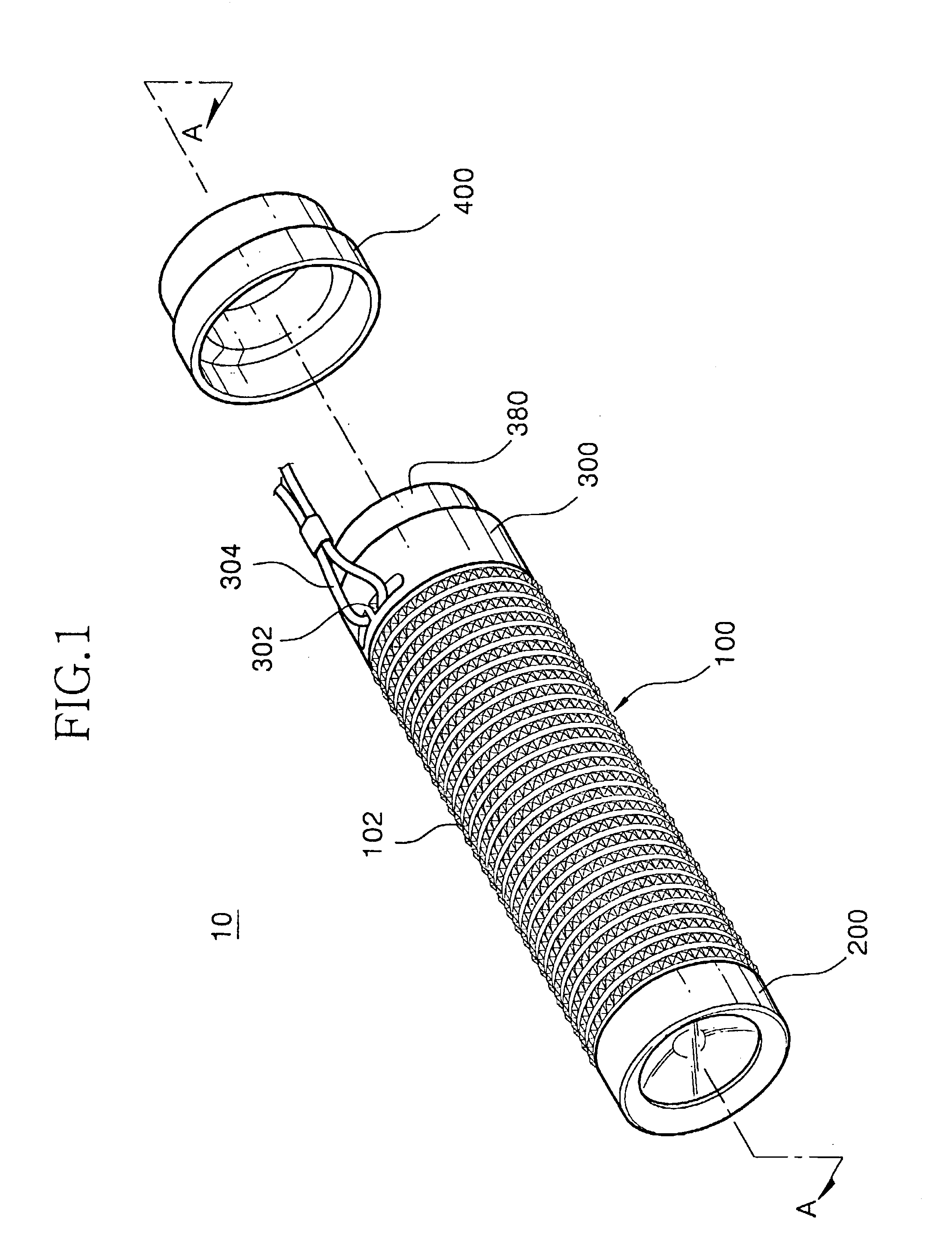
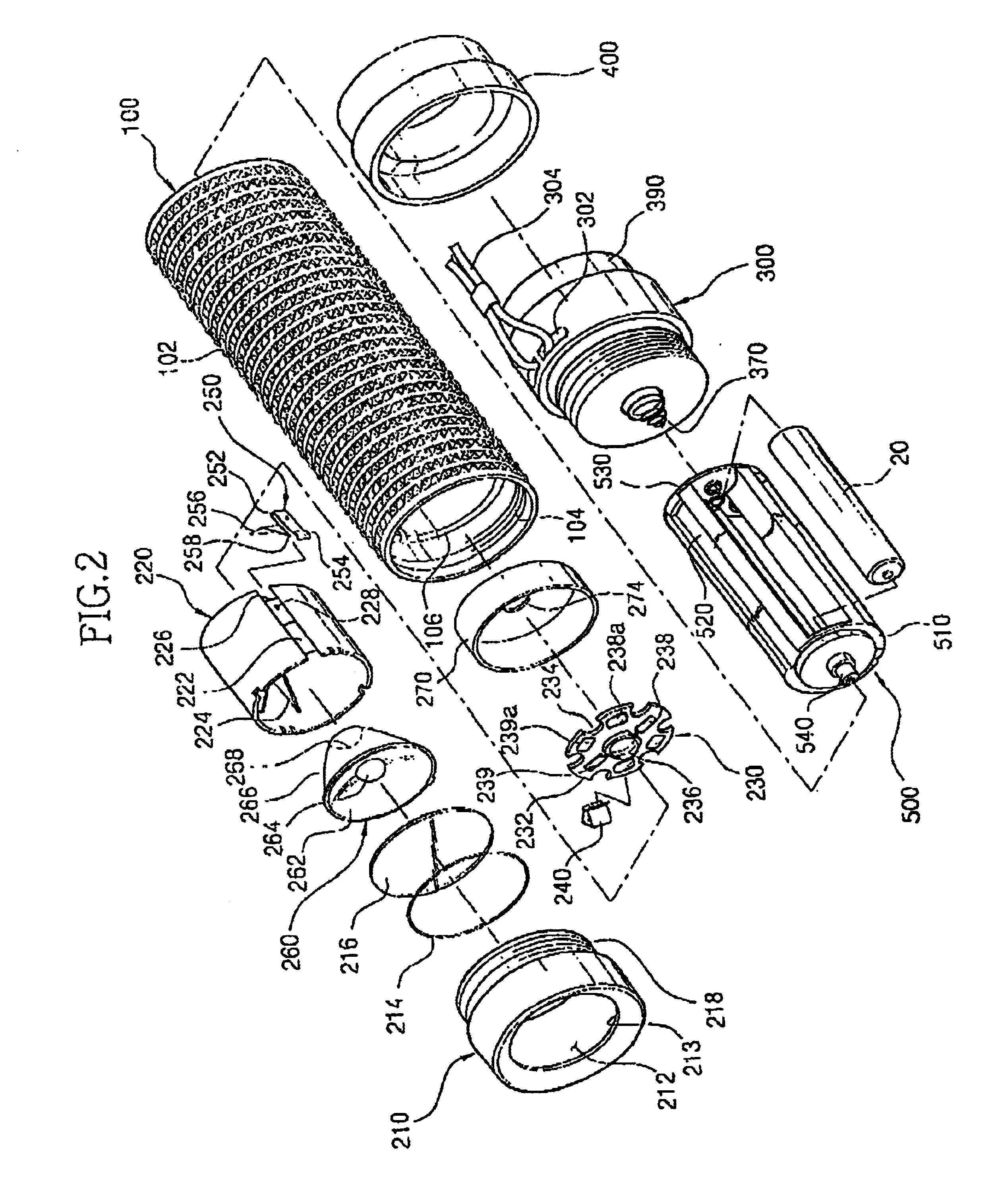
[0078]FIGS. 1 to 5 are views showing a rear push button type single LED flashlight according to a preferred embodiment of the present invention.

[0079]Referring to FIG. 1, a flashlight 10 according to one embodiment of the present invention includes a conductive barrel 100, a head section 200, a tail cap 300 and a rubber cap 400.

[0080]The conductive barrel 100 has a length substantially identical to a width of a palm of an adult's hand. The conductive barrel 100 has a metallic cylindrical structure so as to provide a current path for electrically connecting a negative electrode 24 of a battery 20 to a terminal of a lamp.

[0081]An outer surface of the conductive barrel 100 is formed with a plurality of protrusions 102 so that a user feels a finger-massage effect when gripping the conductive barrel 100. In addition, the protrusions 102 enlarge a surface area of the conductive barrel 100 so that heat generated in the conductive barrel 100 is rapidly discharged out of an exterior. On the ...

embodiment 2

[0129]FIG. 8 is a perspective view of an LED flashlight 60 according to a second embodiment of the present invention, and FIG. 9 is an exploded perspective view of the LED flashlight 60. The LED flashlight 60 of the present embodiment uses C-type battery and a push button switch is provided at a lateral portion thereof. A head section of the LED flashlight 60 is identical to the head section of the LED flashlight described in embodiment 1, so it will not be detailedly described below. The same reference numerals are used to refer the same parts.

[0130]The LED flashlight 60 includes a conductive barrel 130 having a length longer than a length of three C-type batteries aligned in series and an inner diameter larger than an outer diameter of the C-type battery. The conductive barrel 130 has a metallic cylindrical structure to provide a current path for electrically connecting a minus electrode of the battery to one terminal of a lamp.

[0131]A plurality of rubber rings 132 are installed a...

embodiment 3

[0144]FIGS. 11 to 14 are views showing an LED flashlight 80 having a rotary type power on / off manner.

[0145]According to the present embodiment, the LED flashlight 80 includes a conductive barrel 1100, a tail cap 1200, a head case 1300, a head cap 1400, a lamp module 1500, a reflective mirror 1600, and a ring 1700 for discharging heat.

[0146]The conductive barrel 1100 has a length and a diameter adapted for sufficiently accommodating three AA-sized batteries 20 therein, in series. The conductive barrel 1100 has a metallic cylindrical structure providing a current path for electrically connecting a minus electrode 24 of the battery 20 to one terminal of the lamp module 1500.

[0147]The conductive barrel 1100 is formed at an outer surface thereof with a smooth curvature section 1102 having a sine-wave shape, in which a wavelength thereof becomes long from a rear end to a front end of the conductive barrel 1100. The curvature section 1102 is designed according to ergonomics, so that curvat...


PUM


Abstract

Disclosed is an LED flashlight using a high-luminance LED as a lamp. The LED flashlight has a conductive barrel, a conductive tail cap, and a head section. The head section includes a conductive head cap, an insulation case, a lamp module, first and second connecting conductors and a collimator lens. The conductive head cap is detachably coupled to a front end of the conductive barrel and has a transparent window. A front end of the insulation case is inserted into the head cap towards the transparent window. A slot is formed at an outer wall of the insulation case. The lamp module is assembled into an inner rear end of the insulation case and has an insulating substrate including an LED. An anode and a cathode electrode of the LED are formed at a peripheral portion of the lamp module. The lamp module has an insulating substrate formed at a rear surface thereof with a metal layer connected to a positive electrode of a battery. The first connecting connector has a U-shape and is inserted to peripheral portion of the insulating substrate. A first end of the second connecting connector is installed in the slot of the insulation case and a second end of the second connecting connector extends into the insulating case. The collimator lens assembled into the insulation case between the transparent window and the insulation substrate.

Description

CROSS-REFERENCE TO RELATED APPLICATIONS[0001]This application relies for priority upon Korean Utility Model Application Nos. 2002-10255 filed on Apr. 4, 2002 and 2002-33814 filed on Nov. 12, 2002, and the contents of which are herein incorporated by reference in its entirety.BACKGROUND OF THE INVENTION[0002]1. Field of the Invention[0003]The present invention relates to a flashlight using a light emitting diode (hereinafter, referred to as LED) as a lamp (hereinafter, referred to as LED flashlight), and more particularly to an LED flashlight having an improved LED lamp module.[0004]2. Description of the Related Art[0005]Recently, as a semiconductor technology makes great strides, high-luminance LED devices and flashlights using the high-luminance LED devices as a lamp have been variously developed and produced on a commercial scale.[0006]Generally, the LED has a life span about 100,000 hours, which is remarkably longer than the life span of a filament bulb or a discharging lamp, to ...

Claims


Application Information

Patent Timeline
IPC IPC(8): F21V23/04F21V29/00F21L4/00F21L4/02F21V15/01F21V15/00
CPCF21L4/027F21V21/406F21V29/85F21V29/004F21V29/74F21V23/0421F21V5/006F21V15/01F21Y2101/02F21Y2115/10F21V29/87F21V29/89
Inventor YOON, SANG-YEON
Owner AITEC
Why Eureka
Try Eureka