Processes and apparatus for continuous solution polymerization

a technology of continuous solution and polymerization, which is applied in the direction of chemistry apparatus and processes, liquid-gas reaction processes, chemical/physical/physico-chemical processes, etc., can solve the problems of single site catalysts, and inability to fully absorb liquid

Inactive Publication Date: 2005-04-19
EXXONMOBIL CHEM PAT INC
View PDF8 Cites 496 Cited by
  • Summary
  • Abstract
  • Description
  • Claims
  • Application Information

AI Technical Summary

Benefits of technology

[0024]The catalyst is preferably a bulky ligand transition metal catalyst. The bulky ligand contains a multiplicity of bonded atoms, preferably carbon atoms, forming a group, which may be cyclic with one or more optional hetero-atoms. The bulky ligand may be metallocene-type cyclopentadienyl derivative, which can be mono- or poly-nuclear. One or more bulky ligands may be bonded to the transition metal atom. The bulky ligand is assumed, according to prevailing scientific theory, to remain in position in the course of polymerization to provide a homogenous polymerization effect. Other ligands may be bonded or coordinated to the transition metal, preferably detachable by a cocatalyst or activator, such as a hydrocarbyl or halogen-leaving group. It is assumed that detachment of any such ligand leads to the creation of a coordination site at which the olefin monomer can be inserted into the polymer chain. The transition metal atom is a Group IV, V or VI transition metal of the Periodic Table of Elements. The transition metal atom is preferably a Group IVB atom.

Problems solved by technology

Continued polymerization activity during phase separation may influence polymer characteristics undesirably.
The use of single site catalysts is associated with poor solubility in the aliphatic hydrocarbon, saturated, non-polar solvents used for homogeneous solution polymerization.
This in turn can complicate solvent separation to prevent toluene build up in the reactor, and lead to environmental pollution and added maintenance expenditure.

Method used


Image

  • Processes and apparatus for continuous solution polymerization
  • Processes and apparatus for continuous solution polymerization
  • Processes and apparatus for continuous solution polymerization

Examples


example

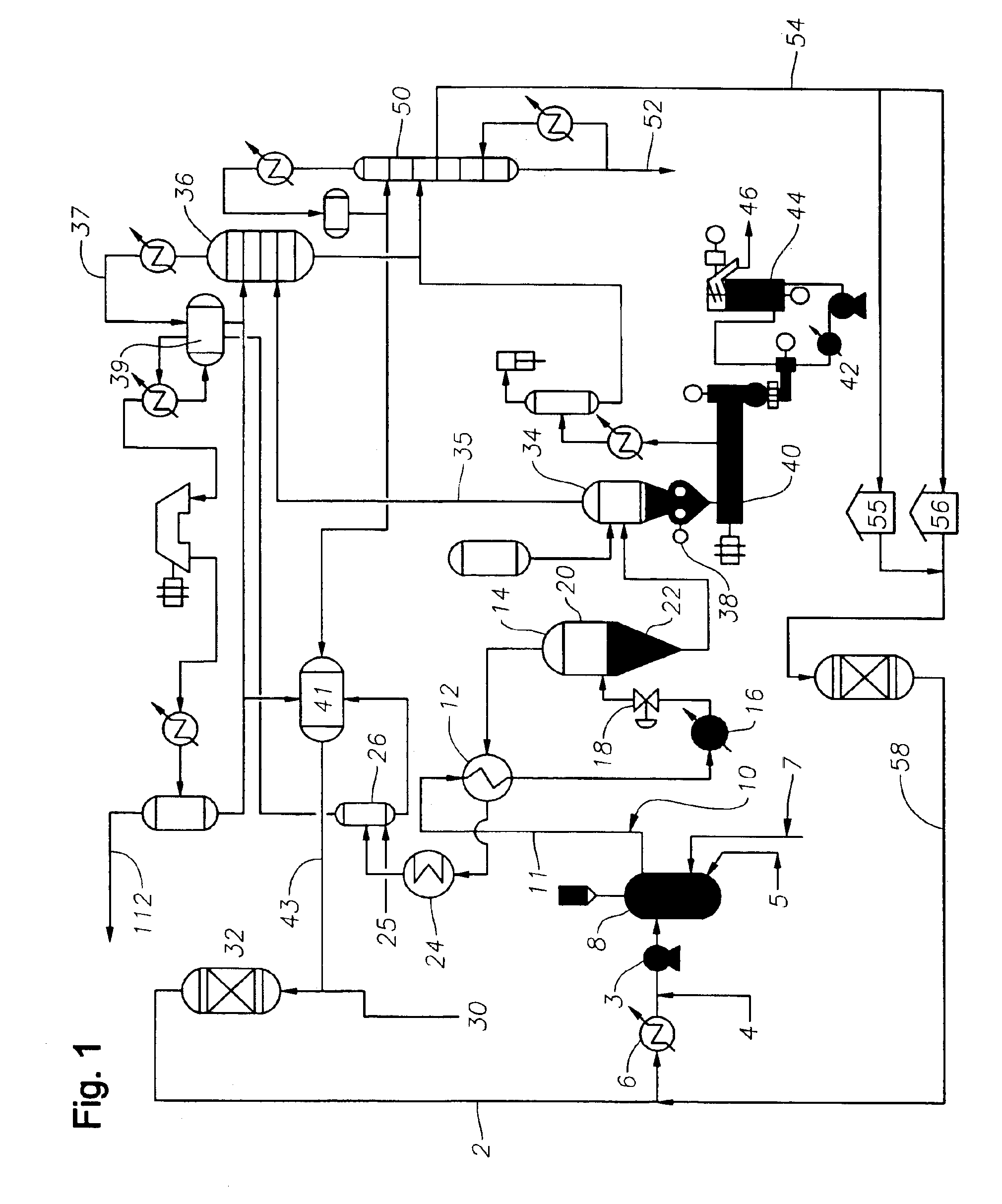
[0082]With reference to FIG. 1 the plant is arranged as follows:

[0083]Polymerization and Initial Separation of Polymer and Solvent

[0084]A feed for polymerization is passed through conduit (2) by a centrifugal pump (3). The feed contains A) hexane as solvent, B) monomer, generally the predominant monomer is ethylene or propylene, and C) comonomer which may be any copolymerizable alpha-olefin, and D) a diene or other polyene or cyclic copolymerizable material. The feed is passed through a chiller or cooler (6) in which the feed is optionally chilled to a low temperature for subsequent adiabatic polymerization in the two continuous stirred tank reactors (8) which are operated in series (for simplicity, only one reactor is depicted in FIG. 1). Activator and metallocene catalyst may be premixed and added at (5) and / or (7) to one or both reactors (8). A scavenger, generally in the form of an alkyl aluminum such as tri-isobutyl aluminum or tri-n-octyl aluminum is next added at (4) to minim...


PUM

PropertyMeasurementUnit
pressureaaaaaaaaaa
pressureaaaaaaaaaa
mol %aaaaaaaaaa

Abstract

The invention relates to processes and plants for continuous solution polymerization. Such plant and processes include a pressure source, a polymerization reactor, downstream of said pressure source, pressure let-down device, downstream of said polymerization reactor, and a separator, downstream of said pressure let-down device, wherein said pressure source is sufficient to provide pressure to said reaction mixture during operation of said process plant to produce a single-phase liquid reaction mixture in said reactor and a two-phase liquid-liquid reaction mixture in said separator in the absence of an additional pressure source between said reactor and said separator.

Description

[0001]This application is the National Stage of International Application No. PCT / US01 / 32299, filed Oct. 17, 2001, which claims the benefit under 35 U.S.C. §119(e) of U.S. Provisional Application No. 60 / 243,192, filed Oct. 25, 2000, the entire disclosure of which is incorporated herein by reference.FIELD OF INVENTION[0002]The invention relates to processes and apparatus for continuous solution polymerization. The invention relates especially to such processes and apparatus using single site soluble transition metal catalysts, in particular those known as metallocene catalysts. The invention furthermore relates especially to such processes and apparatus that provide for improved control of hydrogen level, and more especially for improving series reactor operation using single site soluble transition metal catalysts.BACKGROUND OF INVENTION[0003]Continuous solution polymerization processes generally involve the addition of catalyst to a monomer and solvent mixture. The mixture may be b...

Claims


Application Information

Patent Timeline
Patent Type & Authority Patents(United States)
IPC IPC(8): B01J19/18B01J19/00B01J10/00C08F2/04C08F2/06B01J19/26C08F2/38C08F210/00C08F210/18
CPCB01J10/002B01J19/18B01J19/26C08F2/06C08F210/00B01J19/002Y10S526/92B01J2219/00006B01J2219/00033B01J2219/00103B01J2219/00159B01J2219/00162B01J2219/00168B01J2219/00184B01J2219/00272B01J2219/185B01J2219/1943C08F210/18Y10S526/918C08F210/06C08F210/14C08F236/20C08F2500/21C08F2500/25
Inventor FRIEDERSDORF, CHRIS B.
Owner EXXONMOBIL CHEM PAT INC
Why Eureka
Try Eureka