High temperature process for solution polymerization

a polymerization process and high temperature technology, applied in the direction of separation processes, cleaning of hollow objects, lighting and heating apparatus, etc., to achieve the effect of reducing the stress force of fluid and reducing the amount of fouling

Active Publication Date: 2010-01-26
NOVA CHEM (INT) SA
View PDF33 Cites 55 Cited by
  • Summary
  • Abstract
  • Description
  • Claims
  • Application Information

AI Technical Summary

Benefits of technology

[0028]The current invention provides a simple “on-line” heat exchanger cleaning method. Lowering the pressure at the back end of a heat exchanger deliberately induces a pressure drop across the heat exchanger, which increases the fluid shear stress forces on the “tube side” walls of the heat exchanger. Increasing the fluid shear stress on the walls of the heat exchanger discourages foulant material from accumulating within the heat exchanger tubes and helps to remove deposits that are present.
[0029]In the current invention, lowering the pressure at the back end of a heat exchanger can also induce phase separation of the polymer solution within the heat exchanger to give polymer lean and polymer rich phases. Formation of a liquid-liquid “emulsion” can provide a large pressure drop across a heat exchangers by increasing the apparent viscosity of the polymer solution, which improves scouring of the heat exchanger tubes. Although phase separation has been used to facilitate solvent / monomer separation from the polymer solution as discussed above, it has not previously been used to facilitate cleaning of a heat exchanger as in the current invention.
[0030]The method of the current invention overcomes problems associated with the addition of chemical cleaning agents such as the separation of high boiling volatiles, toxicity or incompatibility with polar solvents. The method also makes it unnecessary to take a heat exchanger “off line” or to shut down a polymerization reactor in order to clean a heat exchanger. The method leads to considerable improvements in on-stream time between reactor shut downs and to more consistent polymer production rates.

Problems solved by technology

The method also makes it unnecessary to take a heat exchanger “off line” or to shut down a polymerization reactor in order to clean a heat exchanger.

Method used


Image

  • High temperature process for solution polymerization
  • High temperature process for solution polymerization
  • High temperature process for solution polymerization

Examples


examples

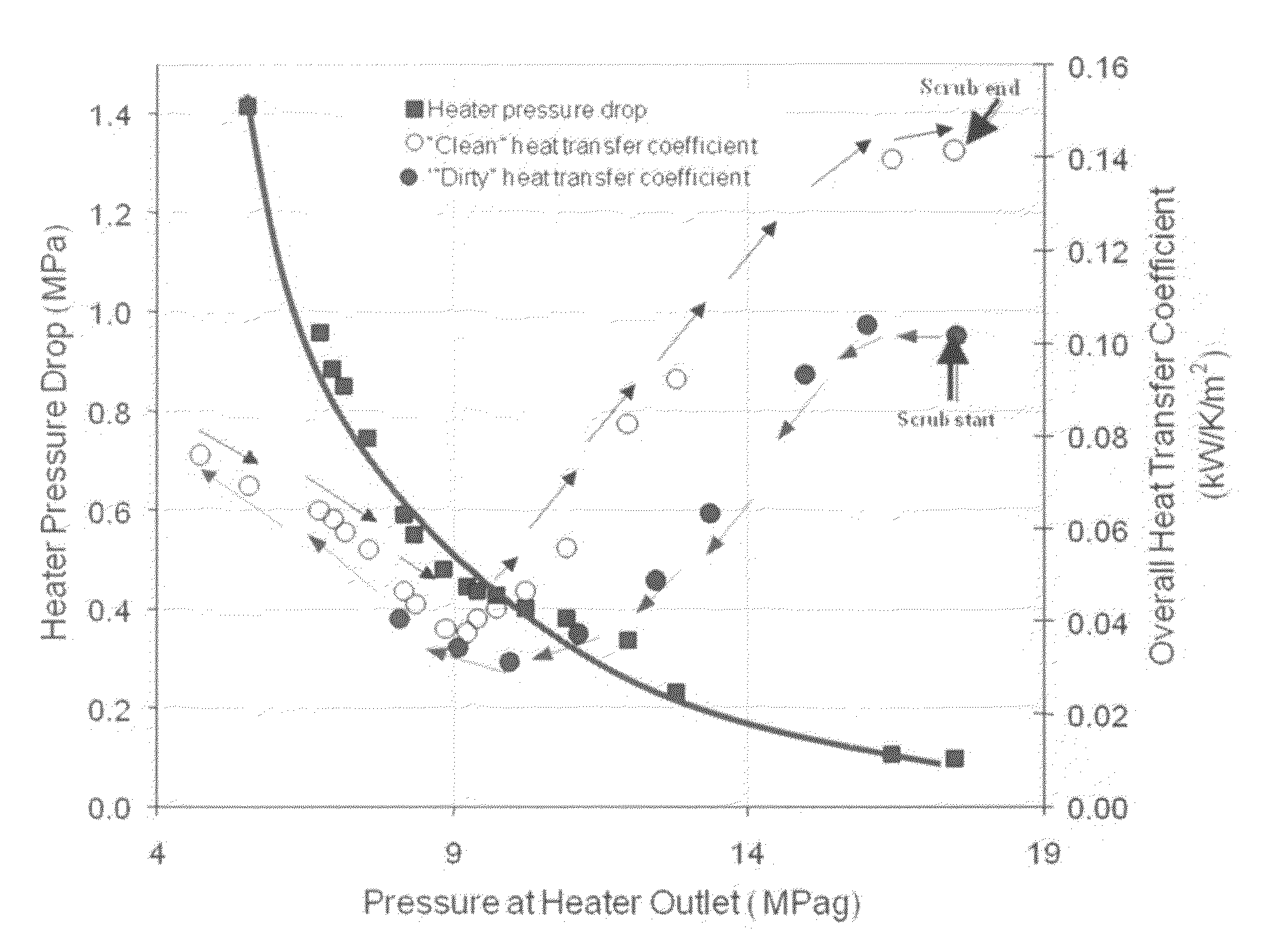
[0145]An example of the heat exchanger cleaning method of the current invention is illustrated in FIG. 5, which displays two plots. The data is for a single shell and tube heat exchanger, which is used to heat a representative effluent polymer solution containing approximately 15 wt % polymer in a hydrocarbon solvent containing a residual amount of ethylene. The flow rate of polymer solution through the heat exchanger was approximately 450 kg / h. The first plot, with ordinate values on the left hand side, shows changes in the pressure drop, (PIN−POUT)TRANSIENT across a heat exchanger due to deliberate changes in the pressure downstream of the heat exchanger, POUT which is plotted on the abscissa. The second plot displays the overall heat transfer coefficient, U, (which is a measure of the heat transfer efficiency of the heat exchanger) also plotted as a function of the heater downstream pressure, POUT. To clean the heat exchanger, POUT was deliberately decreased from about 17 MPag to...


PUM

PropertyMeasurementUnit
mass flow rateaaaaaaaaaa
temperatureaaaaaaaaaa

Abstract

A process for the solution polymerization of olefins with improved on-stream time is provided. The solution polymerization process of the current invention comprises a method for the on-line removal of foulant material from one or more heat exchangers downstream of a polymerization reactor. Removal of foulant material is accomplished by deliberately applying a positive pressure differential across a heat exchanger. In the process of the current invention, reactor shut down is not required for the purpose of cleaning foulant material from a heat exchanger.

Description

FIELD OF THE INVENTION[0001]The current invention provides an improved process for solution polymerization. The solution polymerization process comprises a method for the on-line removal of foulant material from one or more heat exchangers.BACKGROUND OF THE INVENTION[0002]Solution polymerization processes are carried out at temperatures that are above the melting point of the product polymer. In a typical process, catalyst components, solvent, polymerizable monomers and hydrogen are fed under pressure to one or more stirred reactors. Catalyst components may be fed to the reactor as a solution or as a slurry and the temperature of the reactor is controlled by the rate of catalyst addition, the temperature of the catalyst feed stream and / or the use of heat transfer systems. Typical polymerizable monomers for solution phase polymerization processes include ethylene, styrene, propylene and various dienes.[0003]For ethylene polymerization, reactor temperatures can range from about 130° C...

Claims


Application Information

Patent Timeline
Patent Type & Authority Patents(United States)
IPC IPC(8): F28G13/00C08F10/02
CPCC08C2/00C08F6/02C08F10/02C08F2/06C08F2/01C08F110/02Y10S585/95C08F2500/12
Inventor CHELUGET, ERICSOOD, ARUNVANASSELDONK, ROBMCCABE, RYAN
Owner NOVA CHEM (INT) SA
Why Eureka
Try Eureka