
Thermally enhanced metal capped BGA package

Inactive Publication Date: 2005-04-19
ALTERA CORP
View PDF34 Cites 73 Cited by
  • Summary
  • Abstract
  • Description
  • Claims
  • Application Information

AI Technical Summary

Benefits of technology

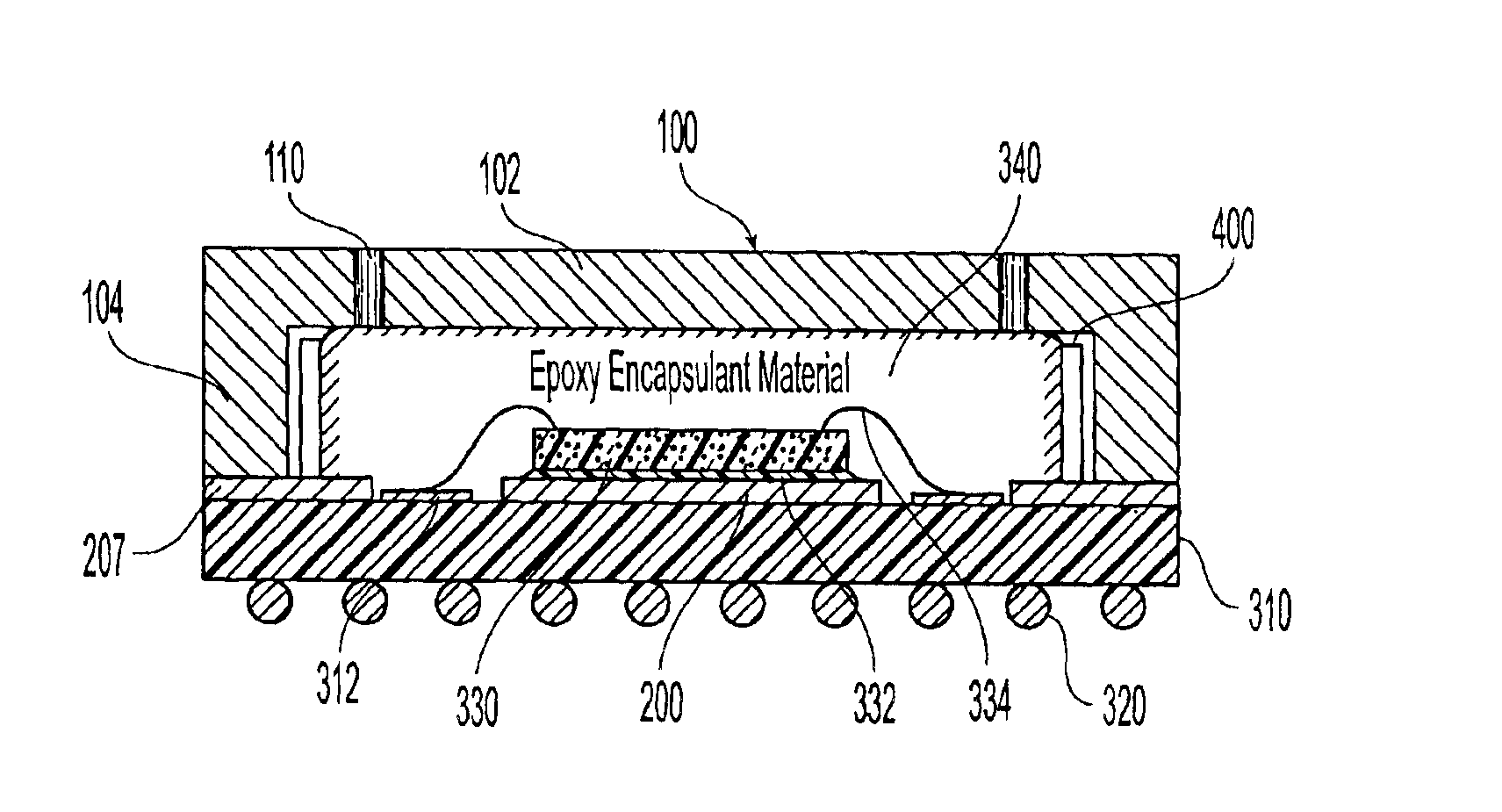
[0008]The epoxy encapsulant material provides a thermal conduction path between the IC device and the metal cap to improve the package's ability to cool the IC device. Also in a preferred embodiment, the thermal conductivity of the epoxy encapsulant material is enhanced by dispersing high thermal conductivity particles in the epoxy encapsulant material. The high thermal conductivity particles are preferably also electrical insulators so that a separate electrical insulation between the IC device and the metal cap is not required.
[0009]Another embodiment of the present invention may incorporate a metal heat slug that is provided between the IC device and the laminate substrate to further enhance the thermal performance of the wirebond BGA package. The metal heat slug has a DAP portion, preferably at least one wirebond pad window portion, and a peripheral rim portion. The metal heat slug is bonded to the top surface of the laminate substrate and the IC device is attached to the DAP portion of the metal heat slug. The metal heat slug may extend out to the peripheral edge portion of the laminate substrate so that the metal cap is attached to the peripheral rim portion of the metal heat slug. In this configuration, the metal heat slug functions as a heat spreader for the IC device and further enhances the thermal performance of the wirebond BGA package by providing a second thermal conduction path between the IC device and the metal cap through the metal heat slug. The metal heat slug is preferably made of a metal or metal alloy having relatively high thermal conductivity such as copper, aluminum or alloys thereof. The metal heat slug may be made of a material with sufficient stiffness so that substrate warping problem sometimes observed after the epoxy encapsulant cure process is minimized.

Problems solved by technology

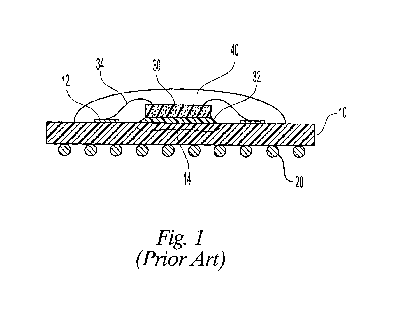
Although these prior art wirebond BGA packages have relatively poor cooling capability, they have been adequate because IC devices used in low-end performance applications have been relatively low powered.

Method used


Image

  • Thermally enhanced metal capped BGA package
  • Thermally enhanced metal capped BGA package
  • Thermally enhanced metal capped BGA package

Examples


Embodiment Construction

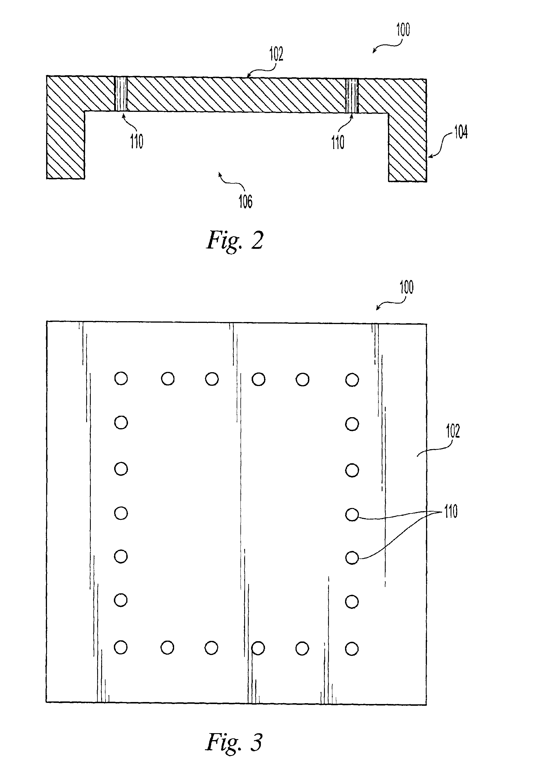
[0017]FIG. 2 illustrates a cross-sectional view of a metal cap 100 according to the present invention. Metal cap 100 has a sidewall portion 104 and a top portion 102 that form an internal cavity 106. Metal cap 100 also has a plurality of holes 110 in top portion 102. Metal cap 100 may be made from metal or metal alloys having relatively high thermal conductivity such as copper, aluminum, or alloys thereof.

[0018]FIG. 3 illustrates a top view of metal cap 100 showing a plurality of holes 110. Metal cap 100 is shown as having a square outline. This particular shape is for illustrative purposes only and the particular outline shape and dimension of a given metal cap would be determined by the particular shape of the laminate substrate to which the given metal cap will be attached.

[0019]FIG. 4 illustrates a top view of a metal heat slug 200 according to an embodiment of the present invention. Metal heat slug 200 has a DAP portion 202 where an IC device would be attached. Along the edge o...


PUM


Abstract

A thermally enhanced wirebond BGA package having a laminate substrate, an IC device mounted on the substrate, and a metal cap defining a cavity inside the package between the IC device and the metal cap. A substantial portion of the cavity is filled with a thermally enhanced epoxy encapsulant establishing a thermal conduction path between the IC device and the metal cap. The BGA package may be further enhanced by bonding a metal heat slug on the laminate substrate and mounting the IC device on the slug.

Description

BRIEF DESCRIPTION OF THE INVENTION[0001]This invention relates to glob top ball-grid array (“BGA”) electronic packages that are thermally enhanced to accommodate higher powered integrated circuit (“IC”) devices, a.k.a. chips.BACKGROUND OF THE INVENTION[0002]Among the variety of electronic packages used in the electronics industry, glob top BGA packages are one of the popular packages for low-end performance applications. Glob top BGA packages are part of a large family of wirebond BGA packages. These wirebond BGA packages utilize low-cost organic material based substrates (a.k.a. laminates) such as Bismaleimide triazine epoxy (“BT”), polyimide, and polytetrafluoroethylene, and are well-suited for the low-end performance applications because of their relatively low cost.[0003]FIG. 1 illustrates a cross-sectional view of such a prior art glob top BGA package. The package consists of a laminate substrate 10 having on one side BGA solder balls 20 and on the opposite side a die attach pa...

Claims


Application Information

Patent Timeline
IPC IPC(8): H01L23/495H01L23/02H01L23/10H01L23/48H01L21/54H01L23/24H01L23/31H01L23/367H01L23/373
CPCH01L21/54H01L23/24H01L23/3675H01L23/3732H01L23/3737H01L2924/16151H01L2924/15311H01L2924/01019H01L2224/73265H01L2224/32225H01L24/48H01L2924/14H01L2224/48227H01L23/3128H01L2924/00012H01L2924/00H01L24/73H01L2924/00014H01L2924/16251H01L2924/181H01L2224/45099H01L2224/45015H01L2924/207
Inventor CHEAH, ENG C.FRITZ, DONALD S.
Owner ALTERA CORP
Learn More