Digital beamforming radar system

a beamforming radar and digital technology, applied in the field of radar systems, can solve the problems of high production cost, high production cost, and high cost of conventional beamforming radars, and achieve the effect of less space and simple manufacturing

Inactive Publication Date: 2005-04-19
COMM & POWER IND
View PDF4 Cites 130 Cited by
  • Summary
  • Abstract
  • Description
  • Claims
  • Application Information

AI Technical Summary

Benefits of technology

[0011]It is an object of the present invention to provide a digital beamforming radar system that is cheaper, requires l...

Problems solved by technology

Analog devices, such as amplifiers, filters, and mixers, which are able to operate at these frequencies, are typically very expensive.
In addition, conventional beamforming radars require a considerable quantity of these analog devices due to the corresponding number of elements in the antenna array.
Accordingly, high production costs have become unavoidable.
However, increasing the number of elements requires a correspondingly greater number of high-frequency analog devices, which also increases the cost of the system.
In ...

Method used


Image

  • Digital beamforming radar system
  • Digital beamforming radar system
  • Digital beamforming radar system

Examples


Embodiment Construction

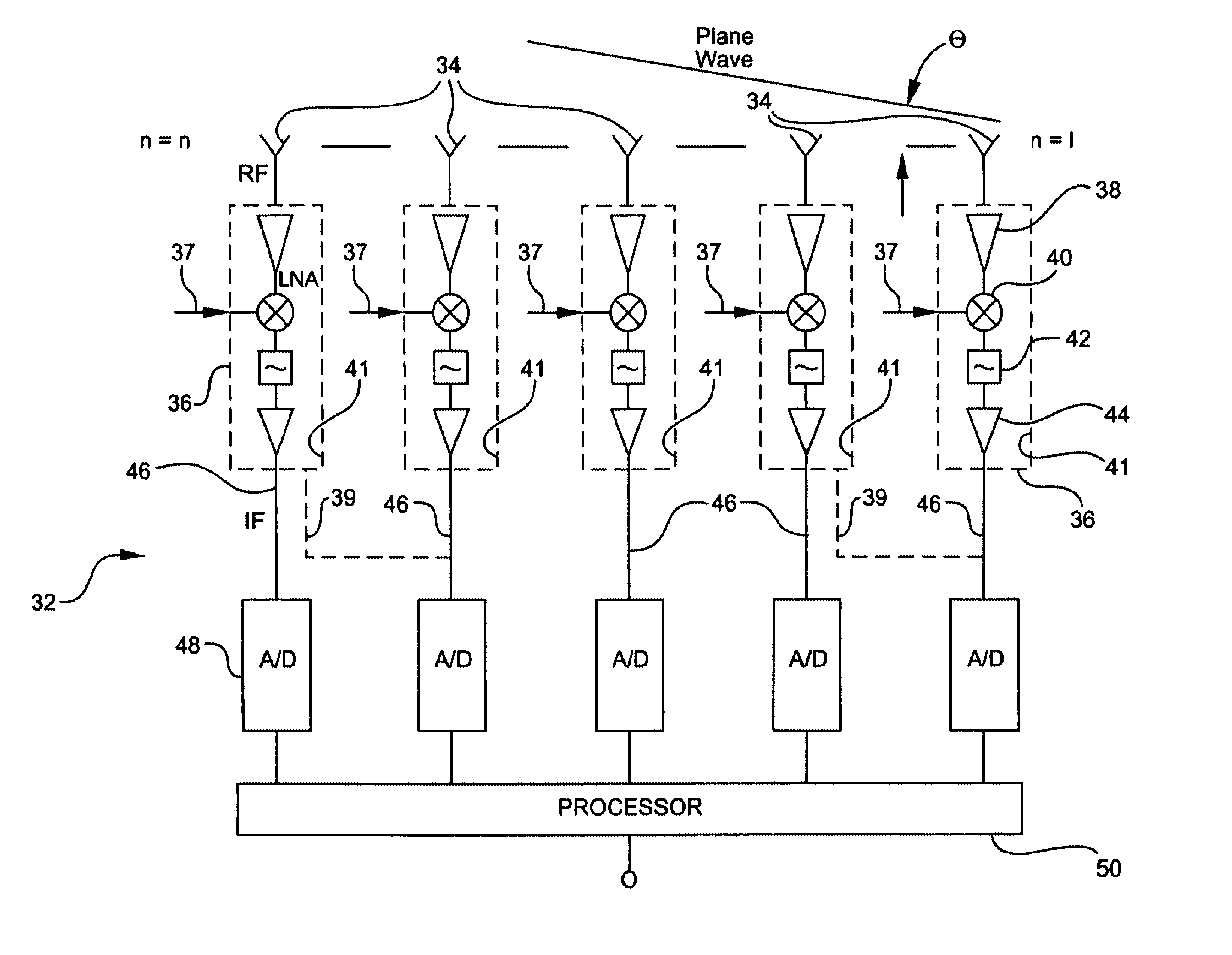
[0030]A preferred goal of the present invention is the illumination of an entire area of interest with a broad transmit beam. The method and system formed in accordance with the present invention utilize commercial off-the-shelf-based (COTS) low-noise receiver and processing components. With these components it becomes possible to simultaneously process a plurality of highly accurate receive beams.

[0031]The present invention preferably utilizes high-speed digital signal processors (DSP) and high-production low-noise block converters (LNB) to solve digital beamforming radar problems in a cost-effective manner.

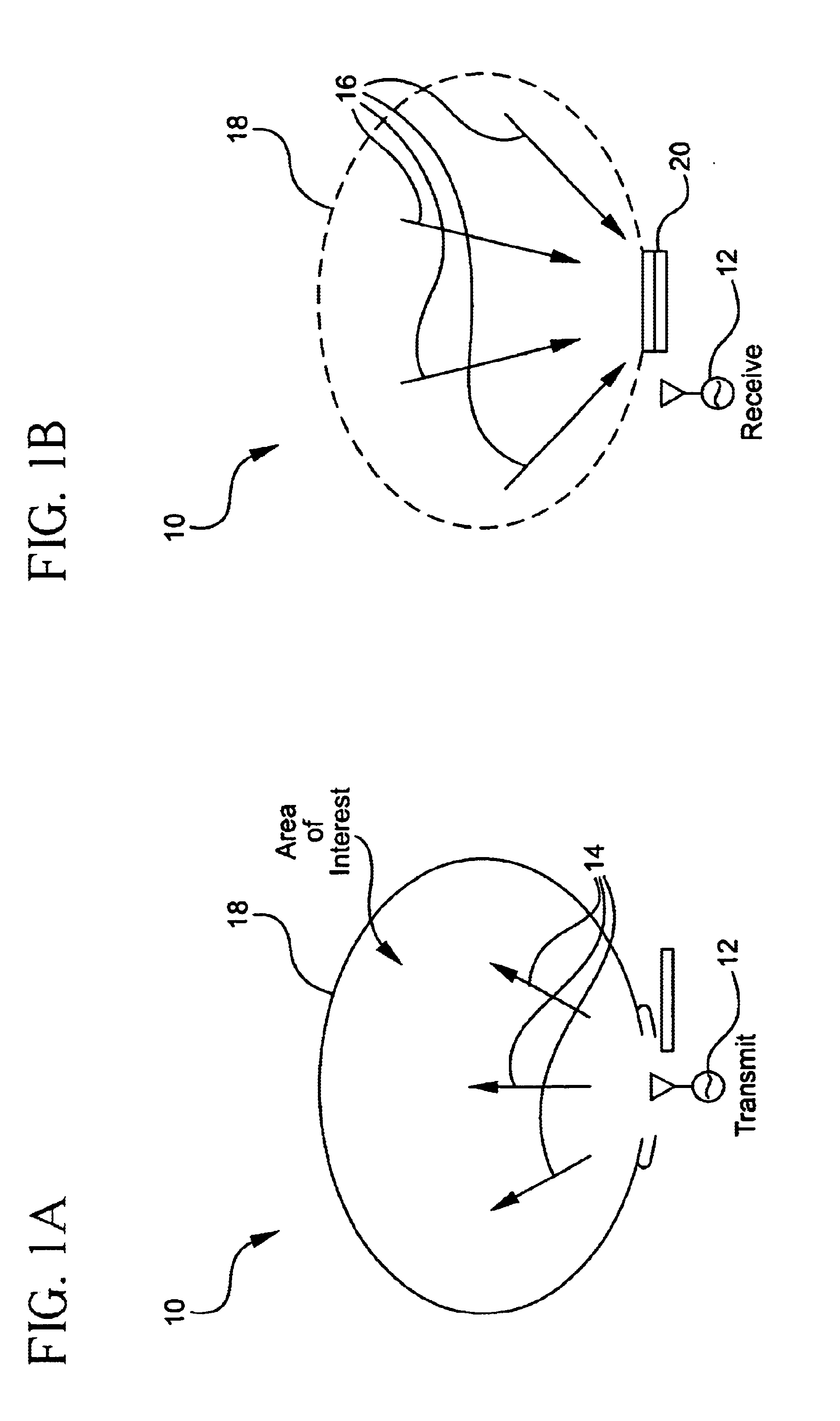
[0032]FIGS. 1a and 1b show a top level representation of a preferred physical embodiment for a radar system 10 formed in accordance with the subject invention. A coverage area 18 of a radar transmit array or aperture 12 is preferably illuminated by broad transmit beams 14, as shown in FIG. 1a.

[0033]Reflected energy 16 from objects within the illuminated coverage area 18 is pref...


PUM


Abstract

A receiver for a digital beamforming radar system includes a plurality of antenna elements, low-noise block converters, one or more analog-to-digital converters, and a processor. The antenna elements receive a radar signal and output a received signal. The low-noise block converters are modified commercially available components used in satellite television systems, respond to the received signal from a corresponding antenna element, and output an intermediate frequency signal. The low-noise block converters include at least one amplifier, a mixer, and a local oscillator input. The local oscillator input enables an external local oscillator signal to be inputted to the mixer. The analog-to-digital converters are responsive to the intermediate frequency signal of a corresponding low-noise block converter. The processor is responsive to the digital signals output by the analog-to-digital converters.

Description

CROSS-REFERENCE TO RELATED APPLICATION[0001]This application claims the benefit of U.S. Provisional Application No. 60 / 283,457, filed Apr. 12, 2001, which is incorporated herein by reference.BACKGROUND OF THE INVENTION[0002]1. Field of the Invention[0003]The present invention generally relates to radar systems and more particularly to a digital beamforming radar system that utilizes a modified commercially available low-noise block converter (LNB) in a receive signal path.[0004]2. Description of the Prior Art[0005]In conventional digital beamforming radar systems, an amplifier, mixer, filter, and analog-to-digital converter are connected to elements of an antenna array. Signals from respective analog-to-digital converters are then subjected to various beamforming algorithms in a digital processor.[0006]In general, digital beamforming radars utilize high-frequency electromagnetic waves, such as microwaves or millimeter waves. Analog devices, such as amplifiers, filters, and mixers, w...

Claims


Application Information

Patent Timeline
IPC IPC(8): H01Q21/00
CPCH01Q21/0025
Inventor WALKER, JOEL F.GONZALEZ, DANIEL G.KELKAR, ANANDLAMARRA, NORMAN
Owner COMM & POWER IND
Why Eureka
Try Eureka