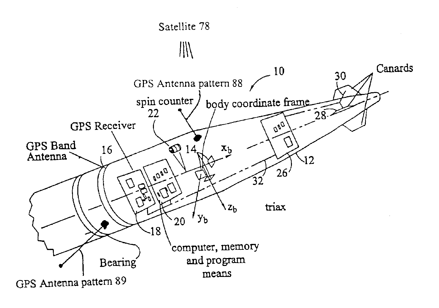
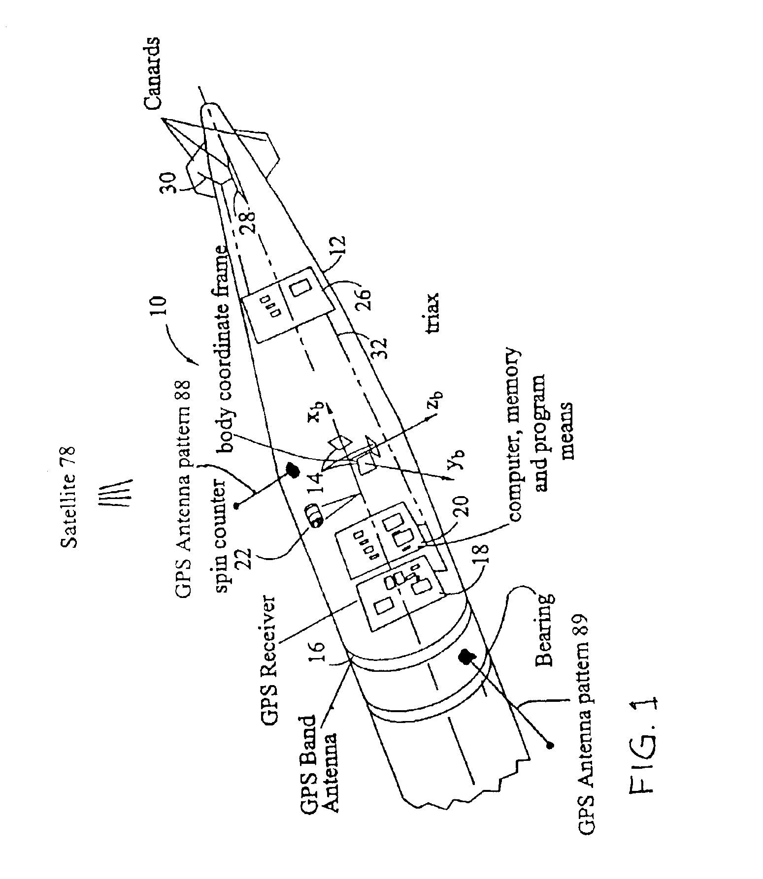
[0011]In an exemplary embodiment, the divert propulsion means comprises one or more aerodynamic surfaces located substantially within the projectile. In accordance with this embodiment, an exemplary projectile has one or more supply ports located so as to receive a supply of gas having an elevated total pressure (dynamic head), e.g., located on the leading surface of the projectile. The projectile further comprises one or more exit ports situated so as to enable the gas to exit the projectile at a location where the local static pressure is lower than the pressure realized at the one or more supply ports, e.g., at the side or
trailing edge of the projectile. The supply ports are in fluid communication with the exit ports through gas metering means and gas directing means which are both controlled by the guidance system. By manipulating the quantity of gas received through the supply ports and / or by manipulating the direction and / or velocity of the gas exiting the projectile through the exit ports, the guidance system may effectively guide the projectile onto a target.
[0012]In another exemplary embodiment, a projectile similarly comprises one or more exit ports in fluid communication with a
gas chamber through a similar gas metering means and gas directing means. In accordance with this embodiment,
high pressure gas may be supplied via a
combustion, or other chemical, process conducted within the projectile, by pre-charging the projectile before or during launch, or by any other means known in the art for producing a compressed volume of fluid. Exemplary methods of supplying the
gas chamber include
chemical reaction, e.g.,
combustion, of monopropellants, bi-propellants,
solid propellants, liquid propellants, and
solid / liquid
propellant hybrids. An exemplary method for pre-charging the projectile before launch involves loading the chamber with
compressed fluid and closing the supply port as soon as the chamber is loaded. An exemplary method of pre-charging the projectile during launch involves opening a port in the projectile so as to permit
high pressure gas from within the launch tube (e.g.,
gun barrel) to flow into the chamber and closing the port before, or very shortly after, the projectile exits the launch tube, thereby loading the chamber with compressed gas. Accordingly, the guidance system may manipulate the direction and / or velocity of the gas exiting the projectile through the exit ports to effectively guide the projectile onto a target.
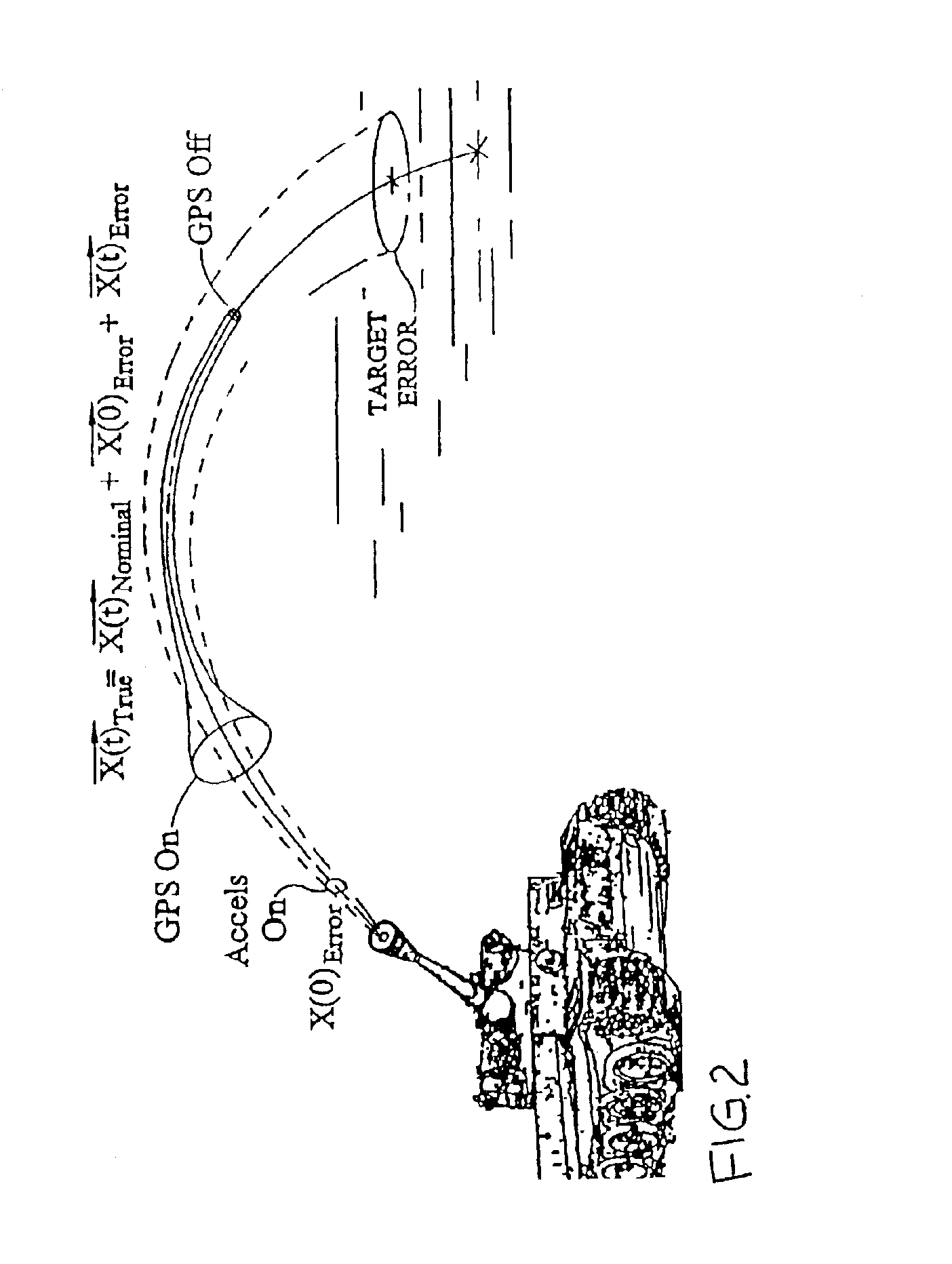
[0013]It should be noted that the cost associated with the guidance system may depend upon the accuracy of the accelerometers that must be used, which depends upon the required delivery accuracy of the projectile. Where cost must be reduced, lower accuracy accelerometers can be used with a greater reliance on GPS signal data after launch. Therefore, to reduce cost while retaining reasonable levels of projectile delivery accuracy, greater reliance must be placed on GPS signal data. Thus, an aspect of the present invention provides for improved reliability of
GPS signals.
[0015]Exemplary GPS signal protection measures may include causing the projectile to engage, or remain engaged, in a periodic motion such as rolling, e.g., via the projectile's divert propulsion means, and using the periodic motion of the projectile to selectively sample
GPS signals in such a manner as to detect and omit jammed GPS signals and to enable reliable
processing of unjammed signals, e.g., by selectively and periodically avoiding GPS signals that exhibit jamming. It should be noted that as a projectile proceeds through each cycle of its periodic motion, i.e., each rolling revolution, each of the one or more antennas will periodically be positioned to receive a GPS signal from each of the one or more satellites. Thus, so long as at least one GPS signal from a
satellite remains capable of being received by an antenna in an unjammed condition, each of the one or more antennas will periodically be free from jamming, e.g., during at least a portion of the roll attitude.


