Turbomachinery blade retention system

a technology of blade retention system and turbine engine, which is applied in the direction of liquid fuel engine, vessel construction, marine propulsion, etc., can solve the problems of increasing centrifugal load and metal temperature, increasing overlap seal design difficulty, and relatively expensive manufacturing

Inactive Publication Date: 2005-04-26
GENERAL ELECTRIC CO
View PDF14 Cites 33 Cited by
  • Summary
  • Abstract
  • Description
  • Claims
  • Application Information

AI Technical Summary

Problems solved by technology

These conditions increase centrifugal loads and metal temperatures, requiring robust turbine blade and blade retainer designs.
However, overlap seals become more difficult to design as centrifugal loads and temperatures increase.
Dovetailed chicklets are challenging to design, especially for single tang blades, and relatively costly to manufacture.
Flowpath gas leakage also occurs through the gaps between adjacent retainers.

Method used


Image

  • Turbomachinery blade retention system
  • Turbomachinery blade retention system
  • Turbomachinery blade retention system

Examples


Embodiment Construction

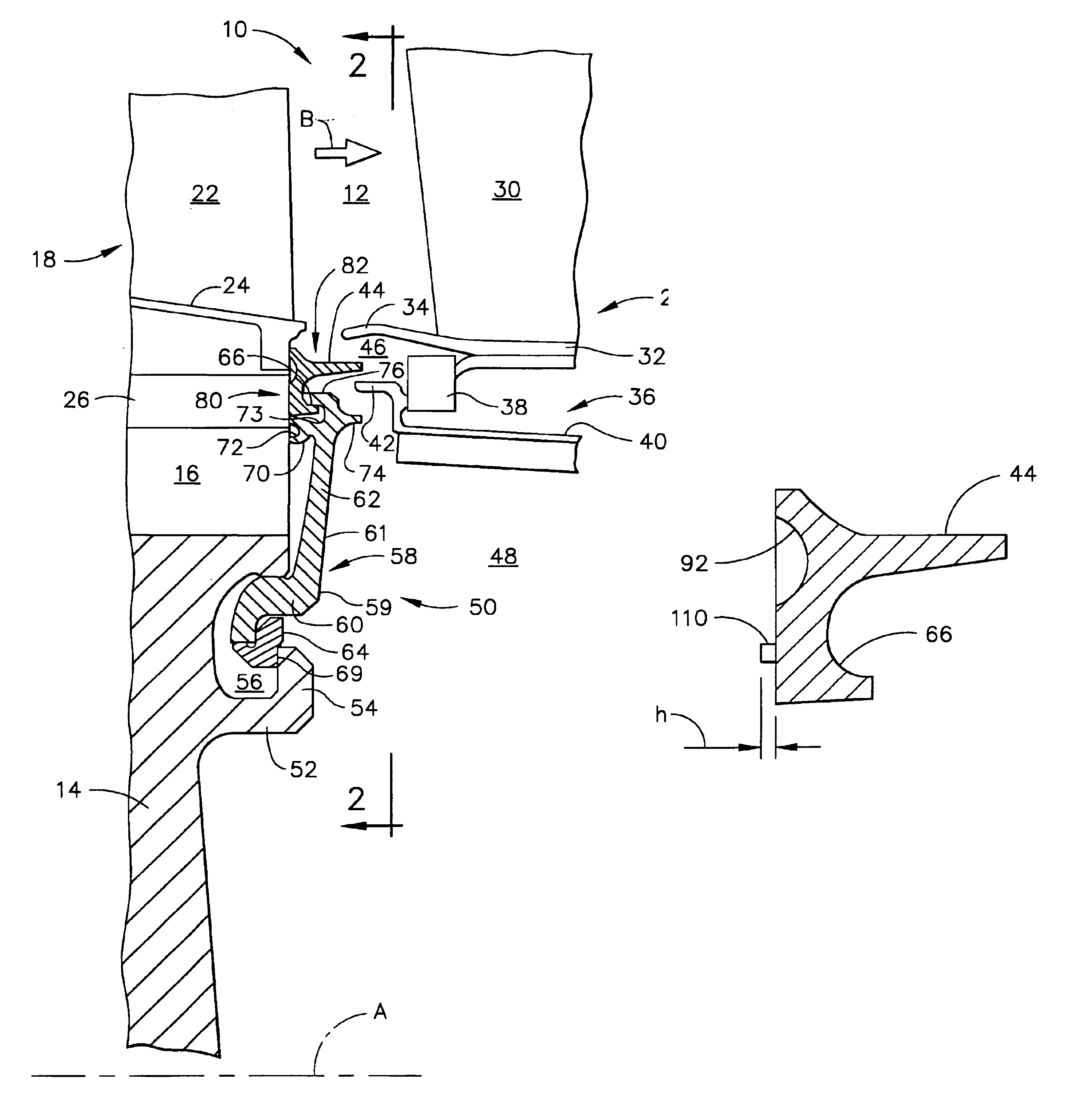
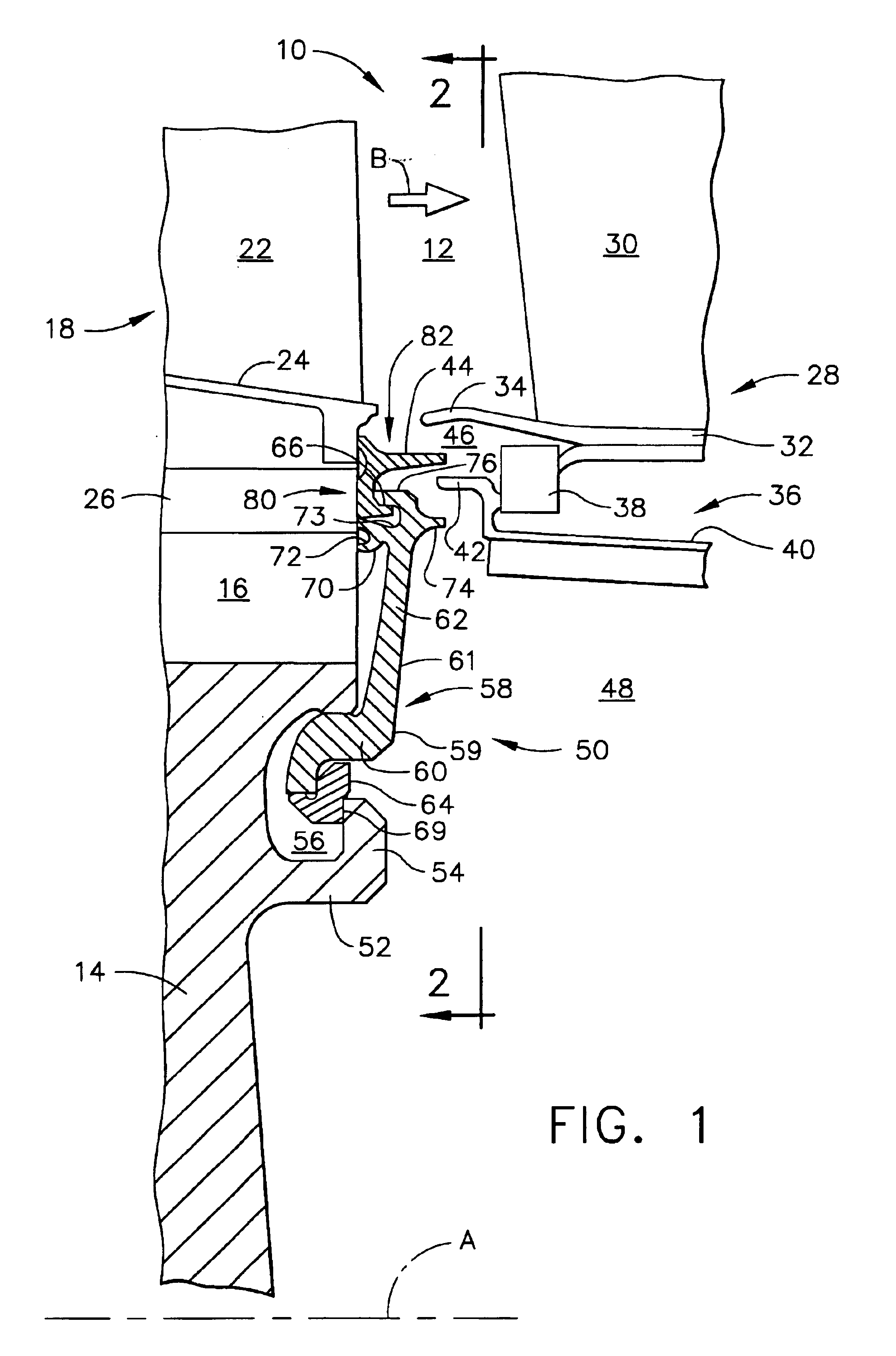
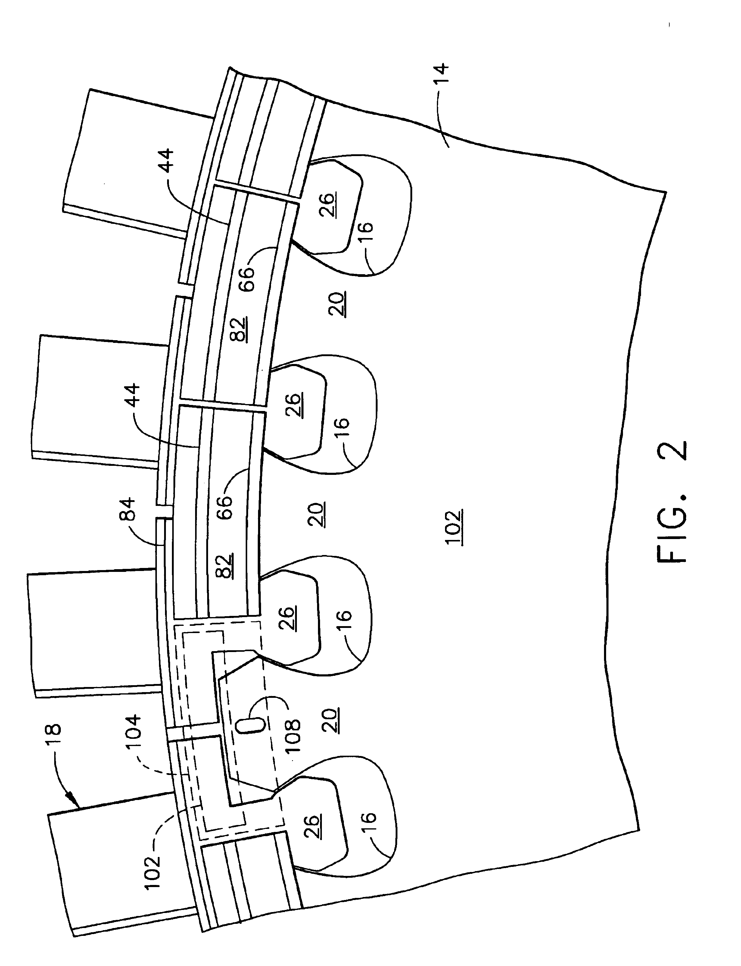
[0015]Referring to the drawings wherein identical reference numerals denote the same elements throughout the various views, FIG. 1 shows a fragmentary cross-sectional view of a turbine rotor assembly 10 of a gas turbine engine which is disposed about a longitudinal axis labeled A. Although a high pressure turbine rotor is shown, the blade retention design of the present invention is equally applicable to other assemblies, such as low pressure turbine rotors or compressor rotors. Combustion gases pass through the flowpath 12 of the rotor assembly 10, generally in the direction of the arrow labeled B. The rotor assembly 10 includes an annular disk 14. The disk 14 has alternating dovetail slots 16 and dovetail posts 20 (see FIG. 2) around its rim. The dovetail slots 16 receive a plurality of turbine blades 18. Each turbine blade 18 comprises an airfoil 22, a platform 24, and a shank 26 which is formed into a dovetail shape complementary to that of the dovetail slot 16. A stator (or noz...


PUM


Abstract

A blade retention assembly is provided that comprises: a disk, a plurality of blades, each having a dovetail disposed in one of an array of slots formed in the outer periphery of the disk, an annular inner retainer attached to the disk, and a plurality of arcuate blade retainers, the blade retainers being secured to the inner retainer by a hooked rabbet joint. A blade retainer is also provided, comprising an arcuate body having a planar inner face having an arcuate depression formed therein defining a sealing lip, and an aft face disposed opposite the inner face which has an arcuate rim formed therein.

Description

STATEMENT REGARDING FEDERALLY SPONSORED RESEARCH & DEVELOPMENT[0001]The U.S. Government may have certain rights in this invention pursuant to contract number NAS3-98004 awarded by the National Aeronautics and Space Administration.BACKGROUND OF THE INVENTION[0002]This invention relates generally to gas turbine engine rotor assemblies and more particularly to a blade retention system for a gas turbine engine rotor assembly.[0003]A gas turbine engine includes a compressor that provides pressurized air to a combustor wherein the air is mixed with fuel and ignited for generating hot combustion gases. These gases flow downstream to one or more turbines that extract energy therefrom to power the compressor and provide useful work such as powering an aircraft in flight. In a turbofan engine, which typically includes a fan placed at the front of the core engine, a high pressure turbine powers the compressor of the core engine. A low pressure turbine is disposed downstream from the high press...

Claims


Application Information

Patent Timeline
Patent Type & Authority Patents(United States)
IPC IPC(8): F01D5/00F01D5/30F01D5/32
CPCF01D5/3015Y02T50/671Y02T50/60
Inventor BRAUER, JOHN CHRISTOPHERLEWIS, KENNETH MARTINHEISE, FRED MARTIN
Owner GENERAL ELECTRIC CO
Why Eureka
Try Eureka