Supercharge Your Innovation With Domain-Expert AI Agents!

Cogeneration system for a fuel cell

a fuel cell and cogeneration technology, applied in electrochemical generators, machines/engines, borehole/well accessories, etc., can solve the problems of endothermic processes, inapplicability, and limited fuel cell development, so as to reduce the size of the cooling system, reduce the size of the stack, and reduce the size of the ancillary power equipment

Inactive Publication Date: 2005-04-26
GENERAL MOTORS COMPANY
View PDF3 Cites 5 Cited by
  • Summary
  • Abstract
  • Description
  • Claims
  • Application Information

AI Technical Summary

Benefits of technology

[0013]In comparison to traditional methods of cooling the fuel cell stack, the present invention allows for a reduction in the ancillary power equipment, a decrease in the size of the cooling system, and a method of the heating the stack in cold start conditions. The system converts the low-grade thermal energy produced by the fuel cell stack to shaft work, and then uses the shaft work to compress and move process air needed by the fuel cell stack. As a result, the electrical motor used to compress process air in conventional systems is displaced, and the size of the stack can be reduced because the electricity requirement of the conventional air compressor it is eliminated. The size of the cooling system is reduced by the amount of energy converted to shaft work. The net result of these two features is a reduction in the size of cooling system radiators, a concern with conventional cooling systems.
[0014]Another benefit of the present invention is that the system may be used heat the fuel cell stack in cold start conditions. The system directs the coolant through a supplemental boiler / super heater when the system is below a predetermined temperature. The supplemental boiler / super heater heats the cooling fluid which in turn heats the fuel cell stack. This greatly reduces the startup time of the system.

Problems solved by technology

Since then most of the fuel cell development has been primarily limited to applications supported by the government such as the United States National Aeronautics and Space Administration (NASA), or in utility plants.
Although compressed or liquefied hydrogen could be used to operate a fuel cell in a vehicle, to date this is not practical.
However, these reforming processes are endothermic and require energy input to drive the reforming reaction.
This energy input and the breakdown of the fuel during the reforming process increases the pressure of the reformer exhaust.
Otherwise, the membrane would flex back and forth, and the catalyst on the membrane that is used to reduce hydrogen molecules would be damaged resulting in poor performance or failure of the system.
These compressed air requirements are a significant drain on the fuel cell system.

Method used


Image

  • Cogeneration system for a fuel cell
  • Cogeneration system for a fuel cell

Examples


Embodiment Construction

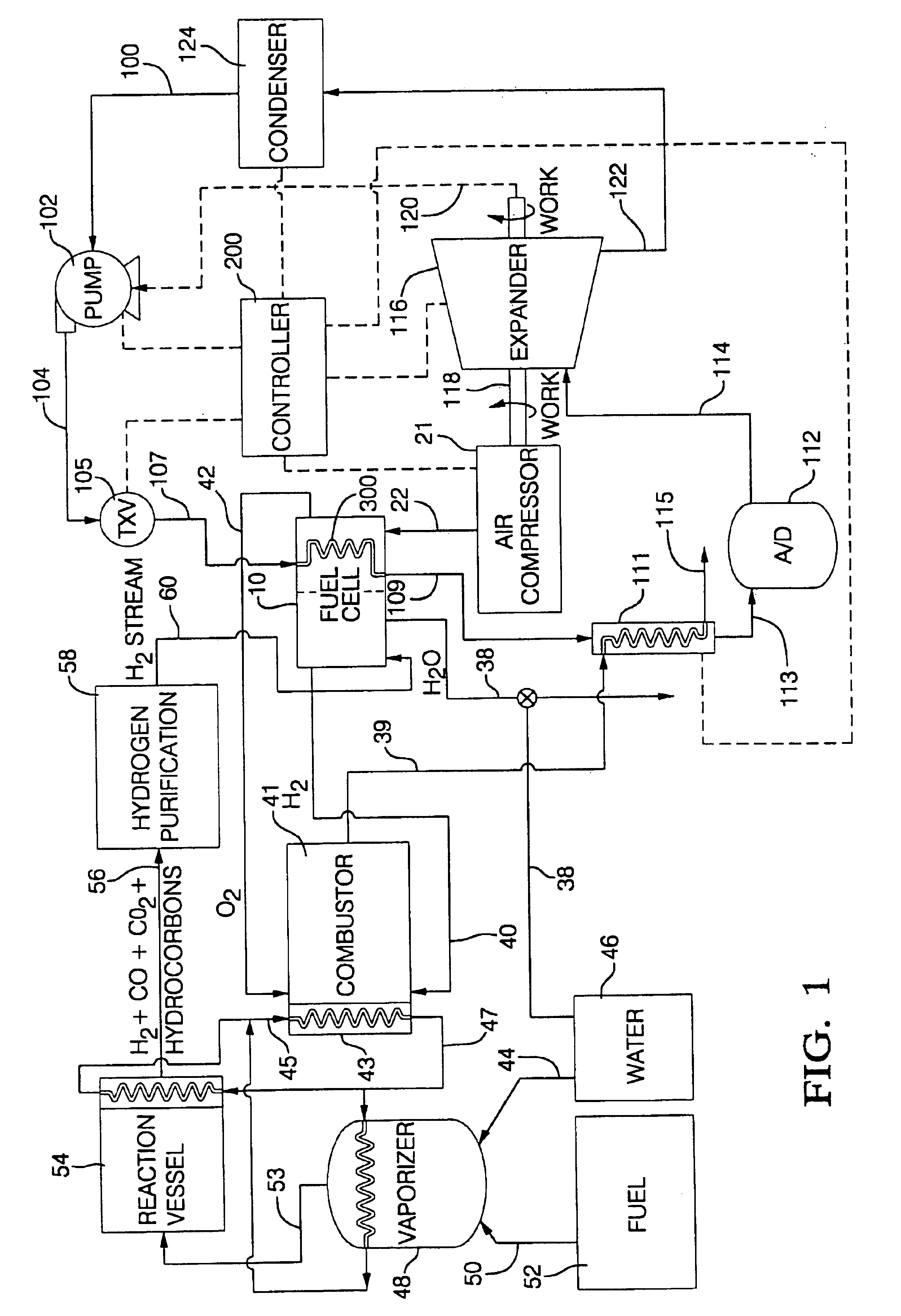
[0018]FIG. 1 illustrates a fuel cell process, system and components useful in the present invention. A water stream 44 from a water source such as a water reservoir or holding tank 46 is supplied to a vaporizer 48. A fuel stream 50 from a fuel holding tank 52 is also delivered to the vaporizer 48. Preferably the fuel stream 50 is an organic based fuel such as methanol or gasoline. The fuel and water are vaporized together and a resulting vaporized fuel / water stream 53 is delivered to a reaction vessel 54, which may in this case be used to perform a fuel reformation process.

[0019]Of course the present invention can be utilized with a variety of different systems besides the fuel reformation process described hereafter. The present invention can be utilized in any system that delivers a fuel to a fuel cell stack for conversion into electricity. For example, the present invention can be utilized with a pure hydrogen system. In such a case, the fuel and water tanks 52, 56, vaporizer 48,...


PUM


Abstract

A fuel cell system and process using an organic Rankine cycle to produce shaft work to operate a fuel cell system component such as an air compressor. The air compressor delivers compressed air to a fuel cell stack. The steps of the Rankine cycle include pumping a liquid working fluid to an elevated pressure, heating the fluid to a gas, expanding the high temperature and high-pressure gas through an expander to produce shaft work used to drive a fuel cell system component such as an air compressor, and then removing energy from the cooling fluid to change the gas back to a liquid, and repeating the cycle. The liquid fluid can be heated by an external boiler, or one of the components of the fuel cell system such as the combustor and / or the fuel cell stack.

Description

[0001]This is a continuation of application Ser. No. 09 / 469,800 filed on Dec. 22, 1999 now U.S. Pat. No. 6,365,289.TECHNICAL FIELD[0002]This invention relates to a fuel cell system having a component that utilizes shaft work.BACKGROUND OF THE INVENTION[0003]Alexander Grove invented the first fuel cell in 1839. Since then most of the fuel cell development has been primarily limited to applications supported by the government such as the United States National Aeronautics and Space Administration (NASA), or in utility plants. However, recent developments in materials of construction and processing techniques have brought fuel cell development closer to significant commercial applications. A primary advantage of fuel cells is that fuel cells can convert stored energy to electricity with about 60-70 percent efficiency, with higher efficiencies theoretically possible. Further, fuel cells produce virtually no pollution. These advantages make fuel cells particularly suitable for vehicle pr...

Claims


Application Information

Patent Timeline
IPC IPC(8): F04F1/00F04F11/00H01M8/04H01M8/00F04F99/00
CPCH01M8/04022H01M8/04029H01M8/04268H01M8/04111Y02E60/563H01M2250/407Y02E60/50
Inventor LEE, JAMES H.SIEPIERSKI, JAMES S.WOODY, GEORGE R.
Owner GENERAL MOTORS COMPANY
Features
  • R&D
  • Intellectual Property
  • Life Sciences
  • Materials
  • Tech Scout
  • Unparalleled Data Quality
  • Higher Quality Content
  • 60% Fewer Hallucinations
Learn More