Intravolume diffractive optical elements

a technology of diffractive optical elements and volume, applied in the field of intravolume diffractive optical elements, can solve the problem of not having accurate mathematical techniques for calculation of such a scattered secondary wav

Inactive Publication Date: 2005-04-26
UCLT
View PDF25 Cites 11 Cited by
  • Summary
  • Abstract
  • Description
  • Claims
  • Application Information

AI Technical Summary

Benefits of technology

[0054]In accordance with still another preferred embodiment of the present invention, the diffractive optical element may be operative to compensate for undesired properties of the incident wave.

Problems solved by technology

Unfortunately, no accurate mathematical techniques exist for calculation of such an accumulated scattered secondary wave.

Method used


Image

  • Intravolume diffractive optical elements
  • Intravolume diffractive optical elements
  • Intravolume diffractive optical elements

Examples


Embodiment Construction

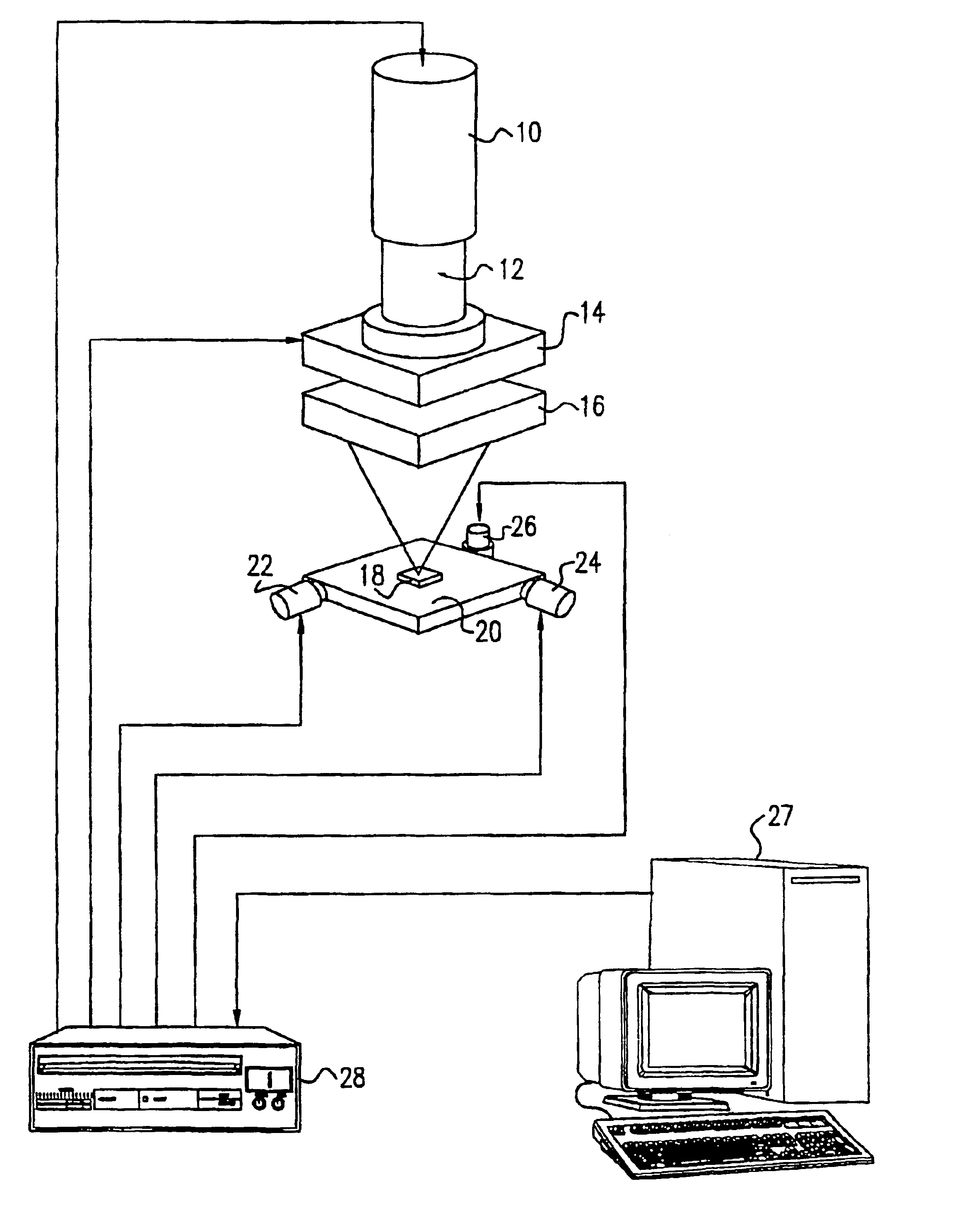
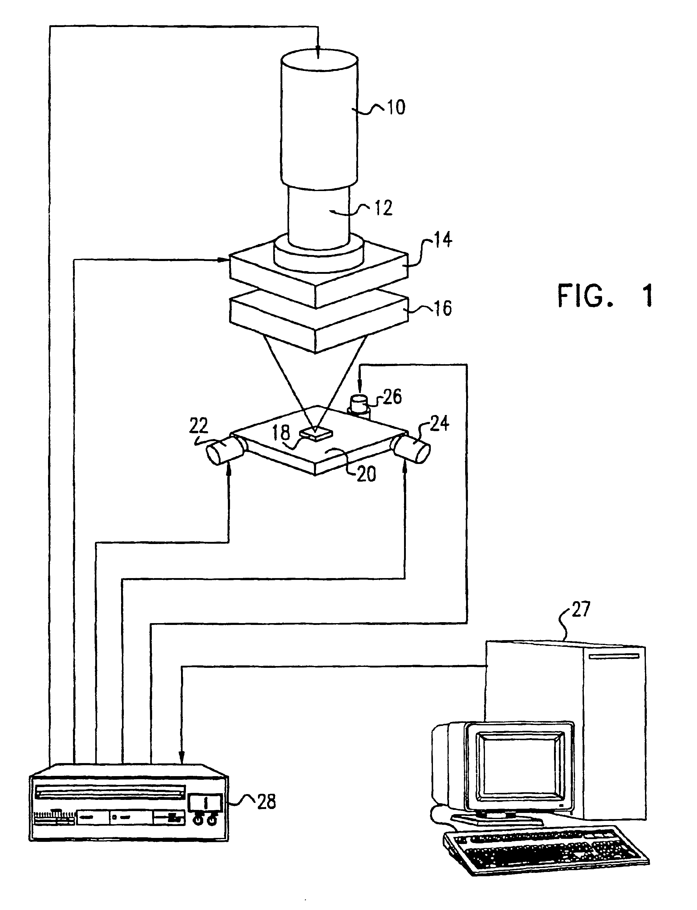
[0071]Reference is now made to FIG. 1, which illustrates schematically a computer-controlled system for the production of 3-dimensional intravolume Diffractive Optical Elements, constructed and operative according to a preferred embodiment of the present invention. A femtosecond pulsed laser 10 emits a beam 12 which is deflected by beam deflector 14 and focused by means of a high quality optical system 16, into a transparent sample 18 in which the DOE is to be produced. The laser pulse peak power is sufficiently high to achieve optical breakdown for the particular material of the sample.

[0072]The sample is disposed on a CNC-controlled three-axis precision stage 20. The motions along the X-Y-Z axes are executed by means of motors 22, 24, 26. Selection of the position at which the spot is to be focused is performed either by motion of the sample using the CNC-controlled motion stage 20, or by means of a the fast optical beam scanner 14, which operates in the x-y plane only, or by a co...


PUM

PropertyMeasurementUnit
diffraction angleaaaaaaaaaa
transparentaaaaaaaaaa
phase propertiesaaaaaaaaaa

Abstract

A method of producing in a solid transparent material, a diffractive optical element for the transformation of an incident wave in a predefined manner, by developing a mathematical model of the element in terms of the required transformation, then using that model for determining a set of points which form the desired diffractie optical element, and then focusing a pulsed laser beam sequentially onto the points in the set, such that it causes optical breakdown damage at those points. Numerical solutions for determining the positions of the set of points from the mathematical model are presented. The production of number of elements for specific applications is described. Complete laser systems capable of monitoring the production of the points in real time according to the results obtained by diffraction of the incident wave by the element under production.

Description

FIELD OF THE INVENTION[0001]The present invention relates to the field of intravolume diffractive optical elements, especially those produced in transparent materials by means of digital laser engraving at very high energy densities.BACKGROUND OF THE INVENTION[0002]Diffractive optical elements (DOE's) are well known and fulfill important roles in industrial and military applications, in imaging, in medicine, in the storage, processing and transmission of information, and elsewhere. Digital DOE's, have been described by B. R. Brown and A. W. Lohmann in the article “Complex Spatial Filtering with Binary Masks”, published in Applied Optics, Vol. 5, p. 967ff, (1966). Such digital DOE's have generally been produced by means of mechanical micro-engraving, electron beam, ion beam or chemical etching, electron lithography or photolithography, or by other suitable techniques.[0003]The mathematical functionality of a DOE can be expressed in terms of the field R({right arrow over (r)}) produce...

Claims


Application Information

Patent Timeline
Patent Type & Authority Patents(United States)
IPC IPC(8): G02B5/32G03H1/08
CPCG02B5/32G03H1/0808G03H2260/62G03H2001/0484G03H2001/0094G03H2001/0491
Inventor DMITRIEV, VLADAMIRGULETSKY, NIKOLAYOSHEMKOV, SERGEY
Owner UCLT
Why Eureka
Try Eureka