Cooling device for electrical subassemblies

a cooling device and electrical subassembly technology, applied in electrical apparatus construction details, separation processes, dispersed particle separation, etc., can solve the problems of device heating up, power loss of components and subassemblies through which current flows lead to heating, and the effect of reducing the volume and weight of the base station, simple cleaning, and advantageous prolongation of the service life of the electrical subassembly

Inactive Publication Date: 2005-04-26
SIEMENS AG +1
View PDF16 Cites 60 Cited by
  • Summary
  • Abstract
  • Description
  • Claims
  • Application Information

AI Technical Summary

Benefits of technology

[0008]The configuration of the arrangement according to the invention has the advantage that, by comparison with cooling arrangements according to the prior art, the interaction of the individual features permits a simpler construction of the cooling arrangement. In this case, in spite of the fact that only one cooling-air stream exists, instead of the two cooling circuits according to the prior art, optimum cooling of the electrical subassemblies is achieved with the required simultaneous protection of the subassemblies from dirt particles and penetrating moisture, and a higher temperature of the ambient atmosphere is permitted, because a temperature difference ΔT does not exist. As a result of the airflow built up by the cooling device, the cooling air heated in the subassemblies is led out of the housing and new cooling air flows into the housing from the ambient atmosphere through the membrane filter. In the process, the cooling air flowing in is freed of dirt particles in the membrane filter, by which means even strict protection regulations can advantageously be satisfied. The membrane filter is designed as a water-repellent surface filter, which advantageously prevents the penetration of dirt particles into the filter and thus permits simple cleaning.
[0010]According to further refinements of the invention, the cooling device comprises a motor-driven fan wheel, the motor speed and thus the throughput of cooling air in the housing in addition being controlled by a control device as a function of the temperature in the housing and / or of the temperature of the ambient atmosphere, and thus of the temperature of the cooling air flowing in. By this means, for example, a constant operating temperature of the electrical subassemblies, and a constant temperature in the interior of the housing, can be ensured, and therefore the service life of the electrical subassemblies can advantageously be prolonged. Furthermore, the speed of the cooling device can in each case be controlled in such a way that the permissible limiting temperatures of the electrical subassemblies are just not exceeded, and the noise emission of the arrangement is minimized by the lowest possible speed of the cooling device.

Problems solved by technology

During operation, technical devices produce waste heat, which leads to the device heating up.
In electrically operated devices, the power loss of components and subassemblies through which current flows leads to heating.
However, the complicated construction of the base station, containing two cooling circuits, has a detrimental effect on the costs, the volume and the weight of the base station.
This construction also has the disadvantage that the cooling arrangement only operates at and above a specific temperature drop between the atmosphere in the interior of the base station and the ambient atmosphere, as a result of which the temperature in the interior is always above the temperature of the ambient atmosphere.

Method used


Image

  • Cooling device for electrical subassemblies
  • Cooling device for electrical subassemblies
  • Cooling device for electrical subassemblies

Examples


Embodiment Construction

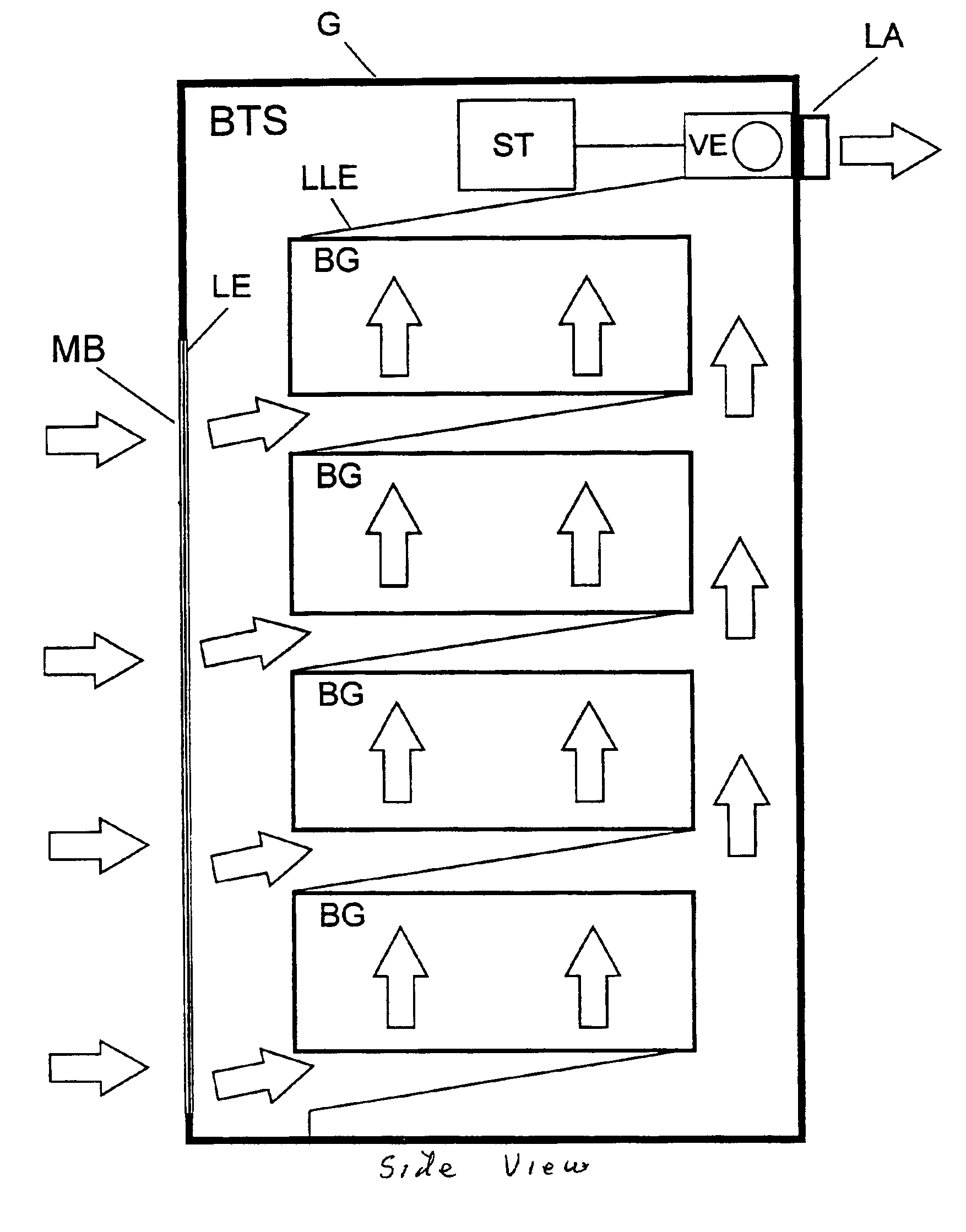
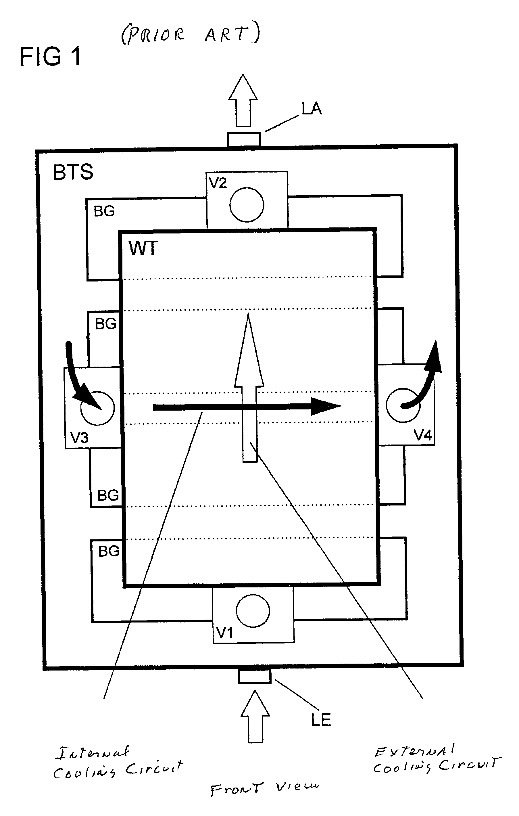
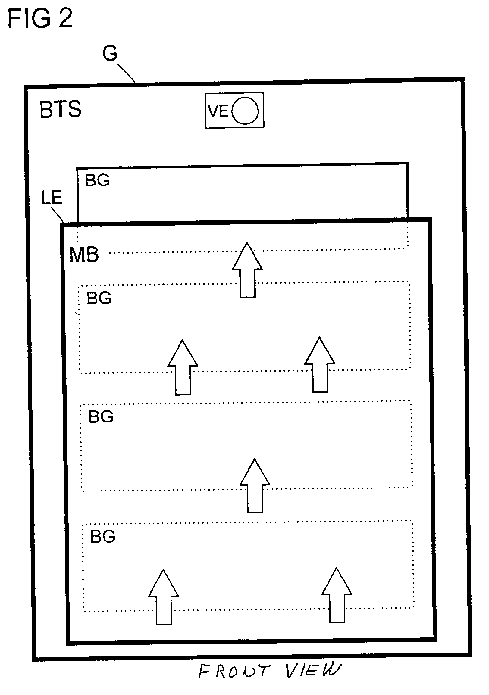
[0021]The base station BTS, for example a mobile radio system according to the prior art device of FIG. 1, contains a number of electrical subassemblies BG. During the operation of the base station BTS, the power loss of the individual electrical subassemblies BG leads to heating, which gives rise to the necessity for cooling. The cooling is carried out by cooling devices VI-V4 incorporated in a number of cooling circuits.

[0022]These cooling circuits are two cooling circuits with one being an external circuit having an air flow identified by white arrows and an internal or second cooling circuit having an air flow identified by black arrows. The two cooling circuits are separated from each other by an air / air heat exchanger WT.

[0023]The external cooling circuit is implemented by two cooling devices V1 and V2. Air at the temperature of the ambient atmosphere is sucked into the base station BTS by the first cooling device V1 through an air inlet LE on one side of the base station BTS....


PUM

PropertyMeasurementUnit
operating temperatureaaaaaaaaaa
temperatureaaaaaaaaaa
water repellentaaaaaaaaaa

Abstract

The invention relates to an arrangement for cooling electrical subassemblies arranged in a housing, in particular for use in base stations of a mobile radio system or access network system. The arrangement has at least one water-repellent membrane filter, in each case arranged in an air inlet of the housing, for the surface filtration of dirt particles from cooling air flowing in for cooling electrical subassemblies, as well as at least one cooling device to build up an airflow and to lead the filtered cooling air, heated because of flowing through the subassemblies, out of the housing through at least one air outlet.

Description

BACKGROUND OF THE INVENTION[0001]The invention relates to an arrangement for cooling electrical subassemblies arranged in a housing, in particular for use in base stations of a mobile radio system or access network system.[0002]During operation, technical devices produce waste heat, which leads to the device heating up. Since a technical device can ensure its functionality only within a restricted temperature range, arrangements for cooling this device are normally provided.[0003]In electrically operated devices, the power loss of components and subassemblies through which current flows leads to heating. If such technical devices are not installed in protected, temperature-controlled rooms, during operation attention must be paid not only to the permissible temperature range of the electrical subassemblies but, at the same time, also to the possible temperature range of the environment of the technical device. Both temperature ranges have to be taken into account when dimensioning t...

Claims


Application Information

Patent Timeline
Patent Type & Authority Patents(United States)
IPC IPC(8): H05K7/20
CPCH05K7/20572H05K7/20
Inventor REECK, GUIDOHOEFER, BRUNOGAHSE, ALFRED
Owner SIEMENS AG
Why Eureka
Try Eureka