Cylinder for internal combustion engine and method of treating inner surface of the cylinder

a technology of internal combustion engine and inner surface, which is applied in the direction of electrophoretic coating, machine/engine, refractive reflector, etc., can solve the problems of non-uniform thickness of plated layer, accompanied plating using dc power, and whisker-like protrusions, so as to promote uniformity and smoothing of plated layer

Inactive Publication Date: 2005-05-03
KIORITZ
View PDF12 Cites 8 Cited by
  • Summary
  • Abstract
  • Description
  • Claims
  • Application Information

AI Technical Summary

Benefits of technology

[0010]It is an object of the present invention to overcome the aforementioned problems. In accordance therewith, the present invention provides a cylinder for an internal combustion engine having an inner surface constituting a piston-sliding surface, which surface has been subjected to a plating treatment to thereby form a high quality plated layer which is uniform in thickness and smooth in surface at low cost without necessitating grinding work such as honing work.
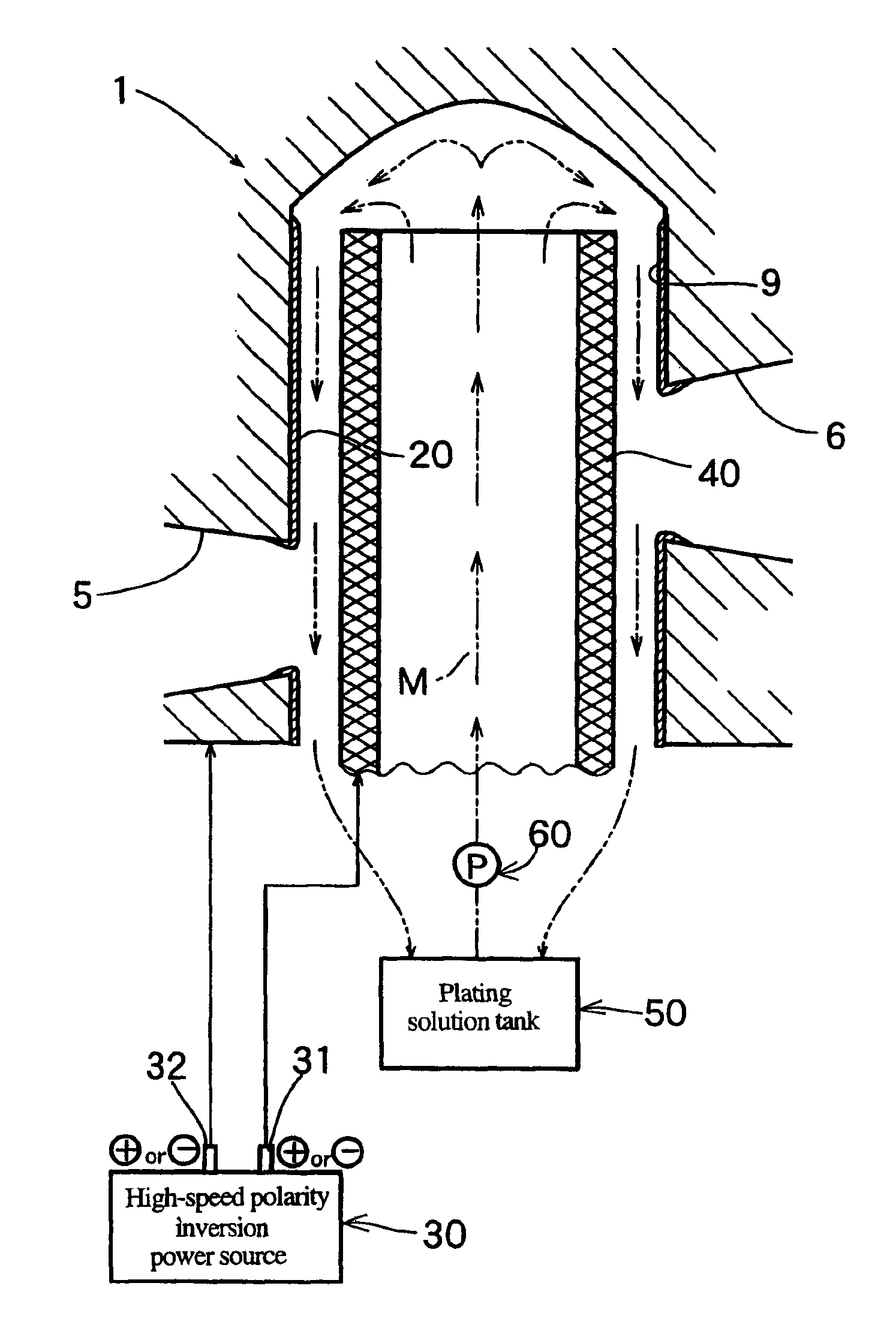
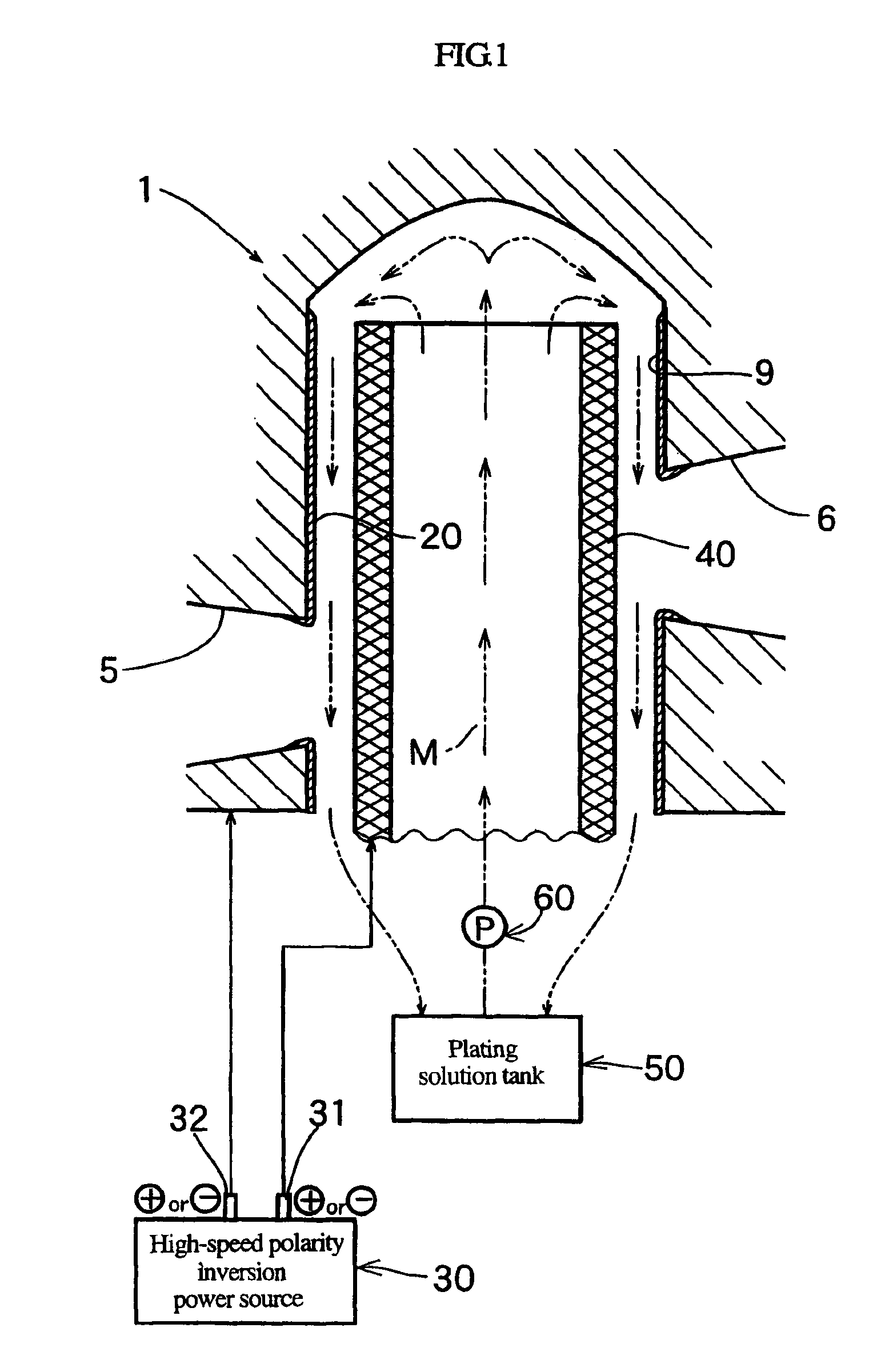
[0015]According to a preferable embodiment, an anode having a cylindrical configuration is introduced into the cylinder and, at the same time, a plating solution is permitted to flow from a plating solution tank to fill the cylinder with the plating solution through the anode and then to flow out of the cylinder to return to the plating solution tank, thereby permitting the plating solution to circulate between the cylinder and the plating solution tank.
[0017]Herein, the PR (Periodical Reverse) method employing a polarity reversal power source is generally known as a method for mainly obtaining glossy plating. In this case, positive electric current (positive power) and reverse electric current (reverse power) are periodically reversed, thereby repeating the generation and dissolution of plated layer. During the time the reverse electric current is being transmitted, protruded portions are preferentially dissolved by electrolytic polishing effects, and during the time the positive electric current is being transmitted, the depolarization effect of the concentration polarization of recessed portions is enhanced, thus promoting the smoothing of the plated layer. This PR method is generally employed in such a manner that the flowing time for the positive electric current is set to a period of 15 to 20 seconds, and the flowing time for the reverse electric current is set to a period of 3 to 4 seconds. If the flowing time for the reverse electric current is too short, the effect of smoothing the plated layer would be minimized. If the flowing time for the reverse electric current is too long, the velocity of plating would be decreased.
[0018]The high-speed polarity reversal power source to be employed in the inner surface treating method according to the present invention has been recently developed mainly as a power source for the copper plating of printed wiring board and is capable, through the control of pulse, of reversing the polarities between positive electric power and reverse electric power at minute intervals of 50 ms or less. Furthermore, this high-speed polarity reversal power source is capable of minimizing polarity reversal loss, and is expected to give improved plated surface-smoothing effects as compared with the case where the conventional polarity reversal power source is employed.
[0024]More specifically, in a first step, the electrolysis is performed for 60 seconds for example, with the integrated positive current / integrated reverse current ratio being selected from the range of 1 to 100, for example selecting 5, thereby allowing a plated layer to deposit on the inner circumferential surface of the cylinder bore. Then, in a second step, the electrolysis is performed for 35 seconds for example, with the integrated positive current / integrated reverse current ratio being selected from the range of 0.01 to 0.9, for example selecting 0.2, thereby allowing the aforementioned plated layer (protruded portion thereof) to dissolve. By doing the electrolysis in this manner, the uniformity and smoothing of the plated layer can be further promoted as compared with the case where the aforementioned integrated positive current / integrated reverse current ratio is fixed to a constant value. However, since the plated layer is permitted to deposit on the surface of the anode during the second step, an additional electrolysis is performed as a third stage taking 60 seconds and selecting the integrated positive current / integrated reverse current ratio from the range of 1 to 100, for example selecting 2.5.
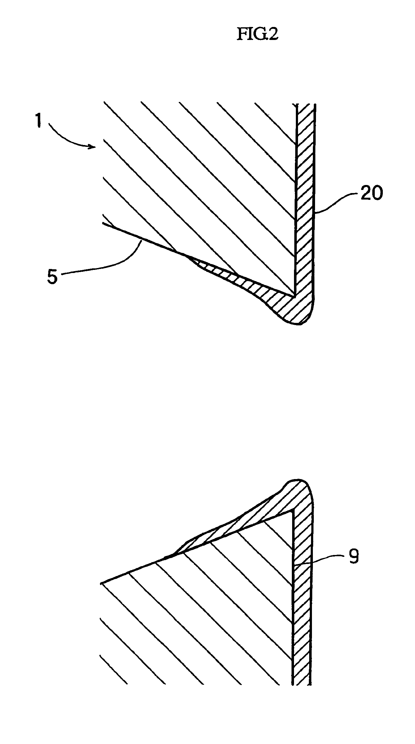
[0025]The plated layer which has been formed on the inner circumferential surface of cylinder bore in this manner is excellent in uniformity of thickness and in smoothness, and still more, the surface hardness of the plated layer is enhanced as compared with the case where the conventional DC power source is employed, thereby rendering the inner circumferential surface of cylinder bore sufficiently endurable for practical use as a piston-sliding surface without necessitating any additional work thereof. Therefore, it is no longer required to perform grinding work such as honing work of the cylinder bore surface after the plating treatment. Namely, only the brushing thereof would be sufficient.

Problems solved by technology

In addition to that, the plating using DC power is also accompanied by a problem in that whisker-like protrusions 10b called “carbon trumpet” are generated (FIG.
3), thereby making the thickness of the plated layer non-uniform and also roughening the surface of the plated layer.
If such protuberance 10a is permitted to exist in the plated layer 10, resulting in non-uniformity and roughness in the surface of the plated layer, the sliding properties of the piston would be deteriorated, making the cylinder unsuitable for practical use.
Therefore, it has been conventionally practiced to form the plated layer 10 in such a manner that, by taking the finishing allowance into consideration, the plated layer 10 is initially formed relatively thick, and then, the resultant plated layer 10 is subjected to grinding work such as honing work of the cylinder bore surface 9 or chamfering work of each of the port portions, thus resulting in increase in manufacturing cost of the cylinder for an internal combustion engine.

Method used


Image

  • Cylinder for internal combustion engine and method of treating inner surface of the cylinder
  • Cylinder for internal combustion engine and method of treating inner surface of the cylinder
  • Cylinder for internal combustion engine and method of treating inner surface of the cylinder

Examples


Embodiment Construction

[0030]The present invention will be further explained with reference to one embodiment of a cylinder for an internal combustion engine according to the present invention.

[0031]The cylinder for an internal combustion engine according to the present invention is made of an aluminum alloy and is designed to be employed in a small air-cooled two-stroke gasoline engine which can be employed in a portable working machine such as a brush cutter, a chain saw, etc. As shown in FIG. 4 illustrating a longitudinal sectional view of the entire structure thereof, the cylinder 1 is constituted by an integral body consisting of a main body 2 provided with a pair of columnar protruded portions 2a disposed diametrally opposite to each other, a head portion 3 having a squish dome-shaped combustion chamber 4 formed therein, and a large number of cooling fins projecting from all over the outer wall of the integral body. Further, the head portion 3 is provided therein with an internal thread 18 for mount...


PUM

PropertyMeasurementUnit
thicknessaaaaaaaaaa
timeaaaaaaaaaa
timeaaaaaaaaaa

Abstract

A cylinder for an internal combustion engine and a method for treating the inner surface of the cylinder, which enables the inner surface constituting a piston-sliding surface of the cylinder to have a high quality plated layer which is uniform in thickness and smooth in surface at low cost without necessitating grinding work such as honing work. The cylinder and the method of the present invention are characterized in that the inner surface of the cylinder is provided with a plated layer which is deposited thereon by a PR (Periodical Reverse) method employing a high-speed polarity reversal power source.

Description

BACKGROUND OF THE INVENTION[0001]1. Field of the Invention[0002]The present invention relates to a cylinder for an internal combustion engine and to a method of treating the inner surface of the cylinder. In particular, the present invention relates to an internal combustion engine made of an aluminum alloy and having a plated inner surface constituting a piston-sliding surface, and to a method of treating the inner surface of the aluminum alloy cylinder.[0003]2. Description of the Related Art[0004]As a typical example of the conventional cylinder for a small air-cooled two-stroke gasoline engine to be employed in a portable power working machine, there is known a cylinder as shown in FIG. 4 (which also illustrates one embodiment of the present invention as explained hereinafter). The cylinder 1 shown in FIG. 4 is formed of an aluminum alloy and constituted by an integral body consisting of a main body 2 provided with a pair of columnar protruded portions 2a disposed diametrally opp...

Claims


Application Information

Patent Timeline
Patent Type & Authority Patents(United States)
IPC IPC(8): C25D5/18C25D5/00C25D7/10F02F1/00C25D7/00F16J10/04
CPCC25D5/18C25D7/10Y10T29/49272C25D5/627C25D5/611
Inventor NOZAKI, KATSUMASATSUCHIYA, SHINJIHASHIBA, MOTOIFUKUDA, HIROSHI
Owner KIORITZ
Why Eureka
Try Eureka