Method for controlling the temperature of an electronic component under test

a technology for electronic components and temperature control, applied in the direction of increasing the damage at fault, heat measurement, instruments, etc., can solve the problems of difficulty in regulating the temperature of a dut, prior art configuration may not be able to efficiently and effectively compensate, etc., to reduce the thermal resistance, and accelerate the thermal response time

Inactive Publication Date: 2005-05-03
DELTA DESIGN
View PDF38 Cites 47 Cited by
  • Summary
  • Abstract
  • Description
  • Claims
  • Application Information

AI Technical Summary

Benefits of technology

[0006]A preferred embodiment of the present invention is realized as a combined heater and heat sink assembly. The assembly can be used in an active thermal control system that regulates the temperature of an electronic device under test (DUT). The assembly is suitably configured to reduce the thermal resistance between the DUT and a thermal cold source or heat sink, while concurrently

Problems solved by technology

However, it can be difficult to regulate the temperature of a DUT if the DUT exhibits rapid or excessive internal temperature changes while being tested; the electronic devices within the DUT often generate hea

Method used


Image

  • Method for controlling the temperature of an electronic component under test
  • Method for controlling the temperature of an electronic component under test
  • Method for controlling the temperature of an electronic component under test

Examples


Embodiment Construction

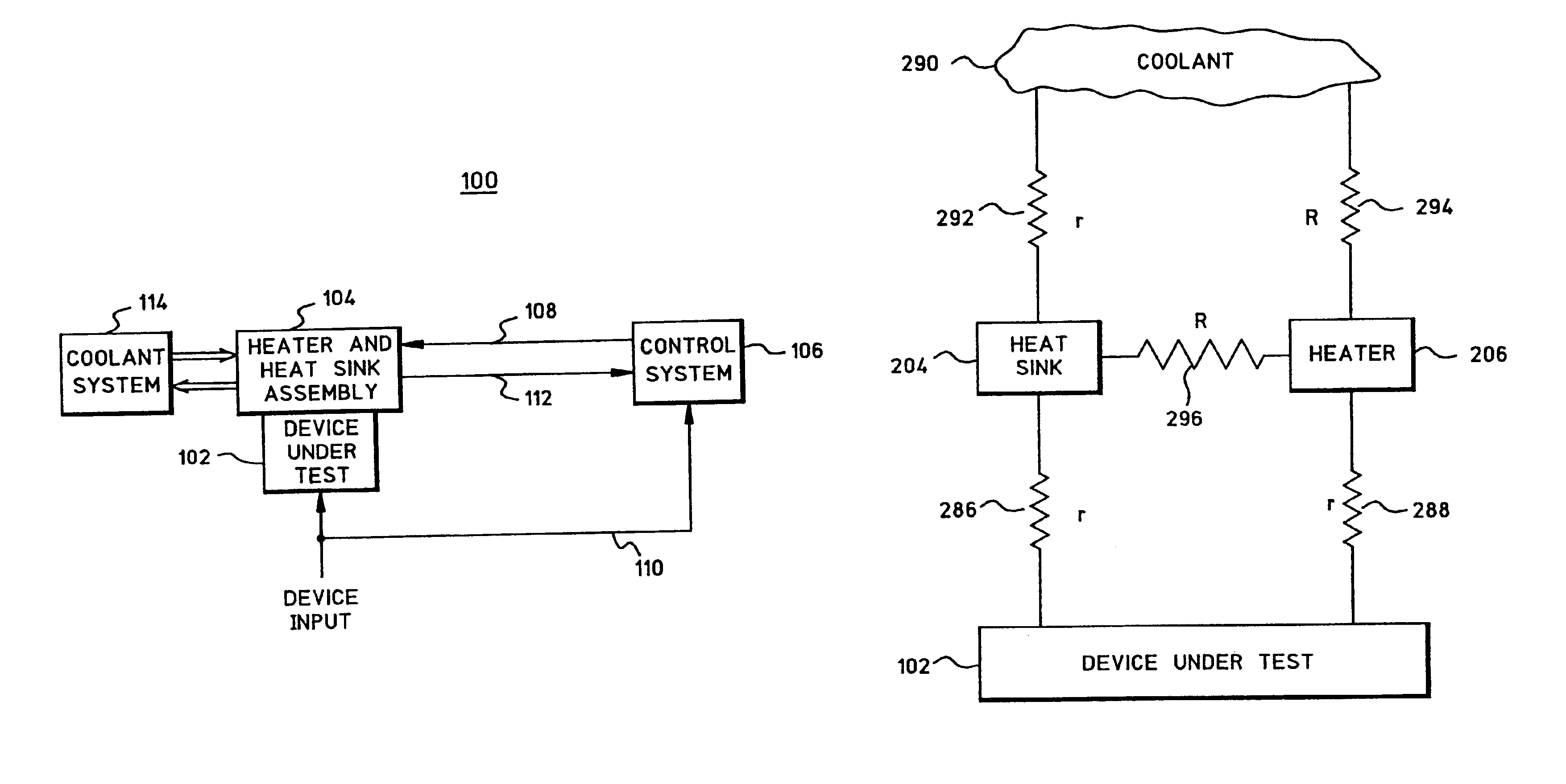
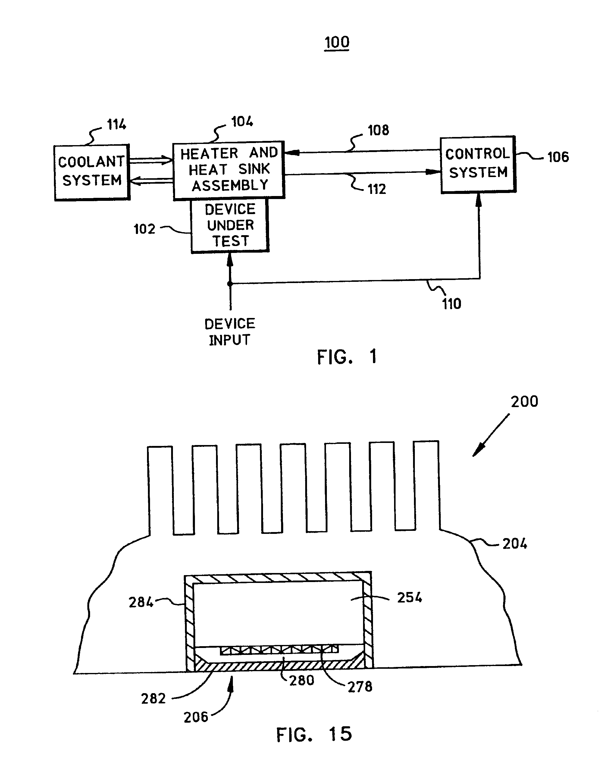
[0025]FIG. 1 is a schematic diagram of an active thermal control (ATC) system 100 for regulating the temperature of a device under test (DUT) 102. For purposes of the example embodiment described herein, DUT 102 is an electronic semiconductor circuit device, such as a microprocessor chip. Alternatively, DUT 102 may be any electronic, mechanical, or other device being subjected to one or more tests performed under specific temperature settings. ATC system 100 may cooperate with a suitable testing system (not shown) that provides a power supply, input signals, and possibly other inputs to DUT 102. A typical testing system also monitors a number of outputs and signals generated by DUT 102 during the test procedure.

[0026]DUT 102 is preferably held against or in close proximity to a heating / cooling assembly 104, which is configured to concurrently provide a hot source and a cold source to DUT 102. In the preferred embodiment, a portion of DUT 102, such as the device lid, contacts heating...


PUM


Abstract

A combined heater and heat sink assembly regulates the temperature of a device under test. The combined heating/cooling assembly includes a heater assembly inlay that is received within a heat sink. The heater assembly includes a heating surface that is coplanar with a cooling surface of the heat sink. In operation, the heating/cooling assembly provides concurrent hot and cold contact points for the device under test. The heater assembly is thermally insulated from the heat sink such that the majority of the heat generated by the heater assembly is directly applied to the device under test; very little of the generated heat is lost to the heat sink. On the other hand, the heat sink provides a relatively low thermal resistance between the device under test and a cold source such as a coolant. Accordingly, the combined heating/cooling assembly provides parallel thermal paths between the device under test and both a hot source and a cold source.

Description

RELATED APPLICATION[0001]This application is a divisional of (and claims the benefit of) U.S. patent application Ser. No. 09 / 829,541, filed Apr. 10, 2001, now U.S. Pat. No. 6,636,062 and titled “Temperature Control Device For An Electronic Component.”FIELD OF THE INVENTION[0002]The present invention relates generally to test equipment for electronic devices. More particularly, the present invention relates to a temperature control device for maintaining constant operating temperature of an electronic device under test.BACKGROUND OF THE INVENTION[0003]Electronic devices, such as integrated circuit chips, are usually tested prior to use. Device manufacturers typically perform a number of electrical and physical tests to ensure that the devices are free from defects and that the devices function according to their specifications. Common types of device testing include burn-in testing and electrical performance testing.[0004]The operating temperature of an electronic device under test (...

Claims


Application Information

Patent Timeline
IPC IPC(8): G01R1/04G01R1/02
CPCG01R1/0458
Inventor GAASCH, THOMAS FRANCISTRIEU, THANH
Owner DELTA DESIGN
Why Eureka
Try Eureka