
Method for producing a hollow fiber membrane module or a capillary membrane module

a technology of capillary membrane and hollow fiber, which is applied in the direction of water/sludge/sewage treatment, moving filter element filters, applications, etc., can solve the problems of easy breakage of hollow fibers, difficult production of hollow fiber membrane modules according to the method of this printed publication, etc., to achieve significant simplified production of hollow fiber membrane modules or capillary membrane modules, the effect of preventing fiber breakage and other defects

Inactive Publication Date: 2005-05-03
FRAUNHOFER GESELLSCHAFT ZUR FOERDERUNG DER ANGEWANDTEN FORSCHUNG EV
View PDF14 Cites 37 Cited by
  • Summary
  • Abstract
  • Description
  • Claims
  • Application Information

AI Technical Summary

Benefits of technology

The present invention provides a method for producing hollow fiber membrane modules or capillary membrane modules using a ceramic or ceramic-containing potting compound. The hollow fibers or capillaries are placed in a mold and the potting compound is then solidified. The resulting module has a simplified production process and is more robust than modules made with a separate mold. The use of a ceramic potting compound prevents fiber breakage and other defects during production. The method also eliminates the need for separate thermal treatment steps and matches the expansion coefficients of the hollow fibers or capillaries with the potting compound to prevent excessive mechanical tension. The hollow fibers or capillaries can be produced by spinning or extruding inorganic or metal organic compounds and the material of the potting compound can be the same or different from the hollow fibers or capillaries.

Problems solved by technology

Production of a hollow fiber membrane module according to the method of this printed publication is, however, difficult as the sintered hollow fibers have a great propensity to break as is characteristic of ceramics.
It is not easy to handle such type sintered hollow fibers so that insertion into the openings of the mold designed as a perforated plate is difficult and can lead to the hollow fibers breaking.
However, in this method too the hollow fibers can break very easily.

Method used


Image

  • Method for producing a hollow fiber membrane module or a capillary membrane module
  • Method for producing a hollow fiber membrane module or a capillary membrane module
  • Method for producing a hollow fiber membrane module or a capillary membrane module

Examples


Embodiment Construction

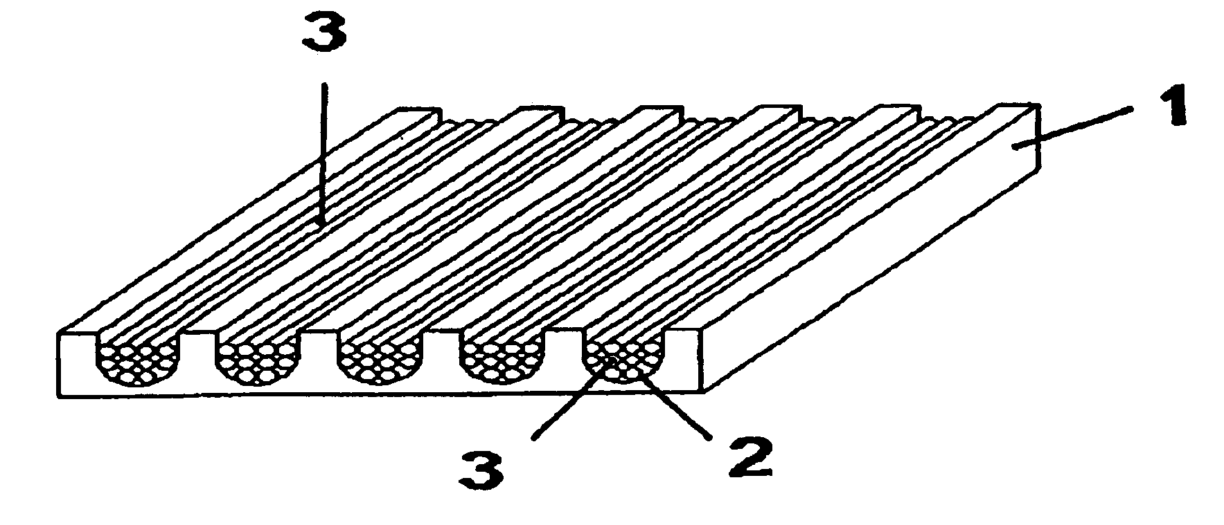
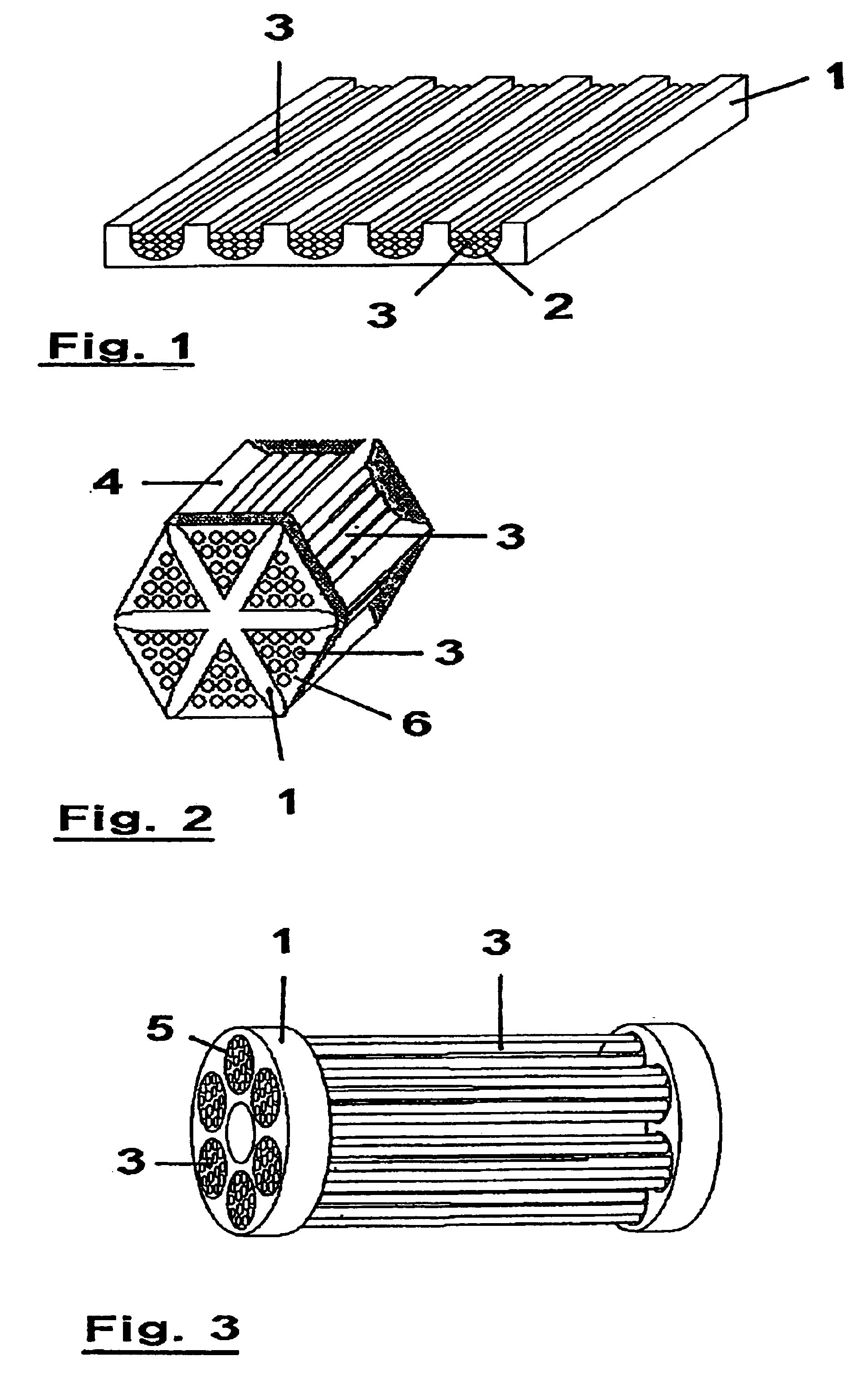
[0036]FIGS. 1-3 show different examples of preferred embodiments of a mold 1, as is utilized in the present method. In the example of FIG. 1, mold 1 is executed as a grooved plate made of ceramic or metal. Hollow fibers 3 in a green state are placed, preferably in bundles, into the grooves 2 of the mold, as the figure shows. Following or simultaneously with the subsequent potting step, these fibers 3 are connected with mold 1.

[0037]The mold (1) of FIG. 2 is designed star-shaped and preferably made of a porous ceramic or porous metal. The hollow fibers 3 in a green state are placed in the recesses 4 formed by the star shape, sintered and simultaneously or subsequently potted.

[0038]FIG. 3 shows a third example, in which mold 1 is formed by two plates provided with hole openings 5. The green fibers are placed in these openings 5 and then sintered and potted. In this manner a module in the form of a multi-channel is formed, as FIG. 3 shows.

[0039]In all three examples, after the potting ...


PUM

PropertyMeasurementUnit
diameteraaaaaaaaaa
diameteraaaaaaaaaa
diameteraaaaaaaaaa

Abstract

The invention relates to a method for producing a hollow fiber membrane module or a capillary membrane module as well as a device having such a module. In the method, hollow fibers or capillaries are placed, in an unsintered state, in a mold structured for receiving the hollow fibers or capillaries and are sintered once inside the mold. Subsequently or simultaneously, the fibers are potted in the mold. The method permits producing hollow fiber membrane modules or capillary membrane modules in a simple manner with little risk of breakage.

Description

BACKGROUND OF THE INVENTION[0001]1. Technical Field[0002]The present invention relates to a method for producing a hollow fiber membrane module or a capillary membrane module in which the hollow fibers or capillaries made of a ceramic or a material with a ceramic content are introduced into a mold structured for receiving the hollow fibers or capillaries and are potted in the mold with a potting compound. In addition, the present invention relates to a device having a hollow fiber membrane module or a capillary membrane module produced according to the present method.[0003]In the present invention, hollow fibers refers to pipe-shaped bodies with an external diameter in the range from approximately >10 μm to 0.5 mm, capillaries refers to bodies with an external diameter between 0.5 and 3 mm.[0004]The present method and device are primarily employed in filtration and separation technology. In these technologies, among other things, inorganic membranes in the form of modules are uti...

Claims


Application Information

Patent Timeline
Patent Type & Authority Patents(United States)
IPC IPC(8): B01D63/02B01D71/02B01D71/00B29C70/00B29C70/76B01D53/22B01D63/00B01D63/06B01D67/00B28B1/00
CPCB01D63/021B01D63/022B01D63/023B01D71/02B29C70/766B01D69/08B01D67/0041B01D2325/22B01D63/0224B01D63/0221B01D67/00411B01D71/0215
Inventor STROH, NORBERTSTEIN-ROEDER, KATJAHOFLER, THOMASHERTERICH, UWE
Owner FRAUNHOFER GESELLSCHAFT ZUR FOERDERUNG DER ANGEWANDTEN FORSCHUNG EV
Learn More