
Integrated air foil and ammonia injection grid for SCR systems

a scr system and air foil technology, applied in the field of integrated air foil and ammonia injection grid for scr systems, can solve the problems of large flue gas side pressure drop between the furnace and the stack, large blockage of a large area of exhaust gas, and high cost of scr catalysts, so as to minimize the unrecoverable pressure loss of the flue system and reduce the unrecoverable pressure loss

Inactive Publication Date: 2005-05-03
THE BABCOCK & WILCOX CO
View PDF2 Cites 44 Cited by
  • Summary
  • Abstract
  • Description
  • Claims
  • Application Information

AI Technical Summary

Benefits of technology

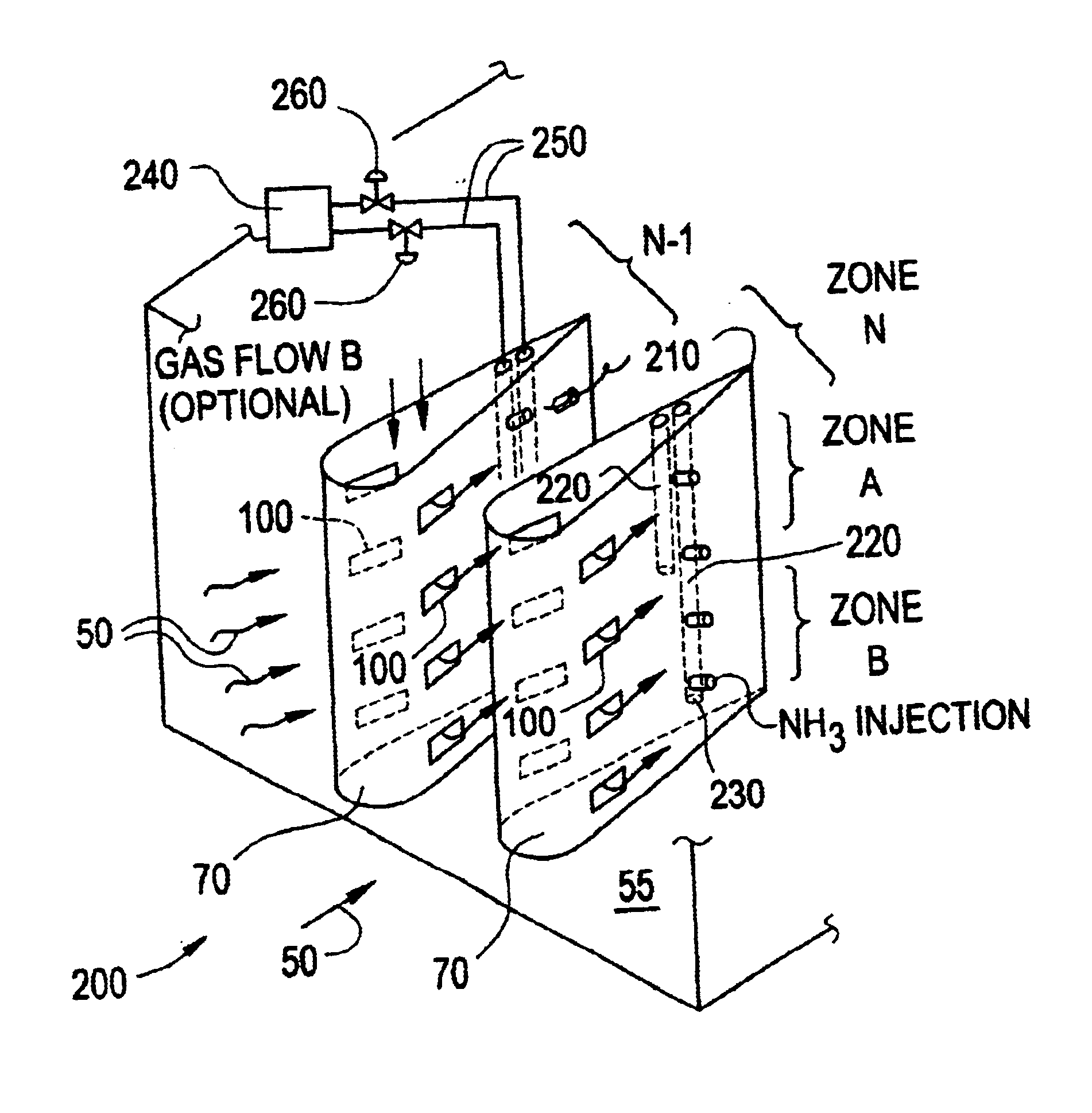
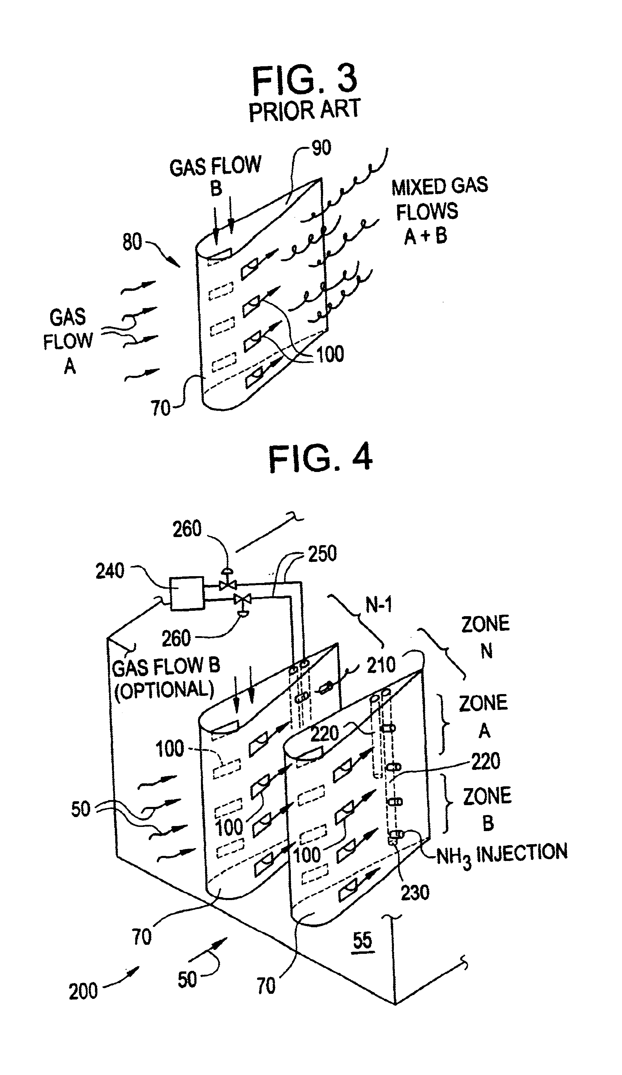
[0013]The present invention integrates an arrangement of air foils with an ammonia injection grid, whereby unrecoverable pressure losses are reduced. This is accomplished by locating a significant portion of the ammonia supply piping inside the air foil structures themselves. The aerodynamic shape of the air foil minimizes the flue system unrecoverable pressure loss. If desired, these same air foils can also be used for gas mixing.
[0014]The integrated air foil and ammonia injection grid according to the present invention minimizes system pressure loss while still achieving distribution of flue gas over the cross section of a flue in which it is installed to minimize thermal gradients. Improved distribution of ammonia into an exhaust gas stream with a desired degree of mixing of the ammonia with the flue gas can also be achieved without the use of a known static mixer device.

Problems solved by technology

The catalysts used in SCR systems are carefully engineered and expensive.
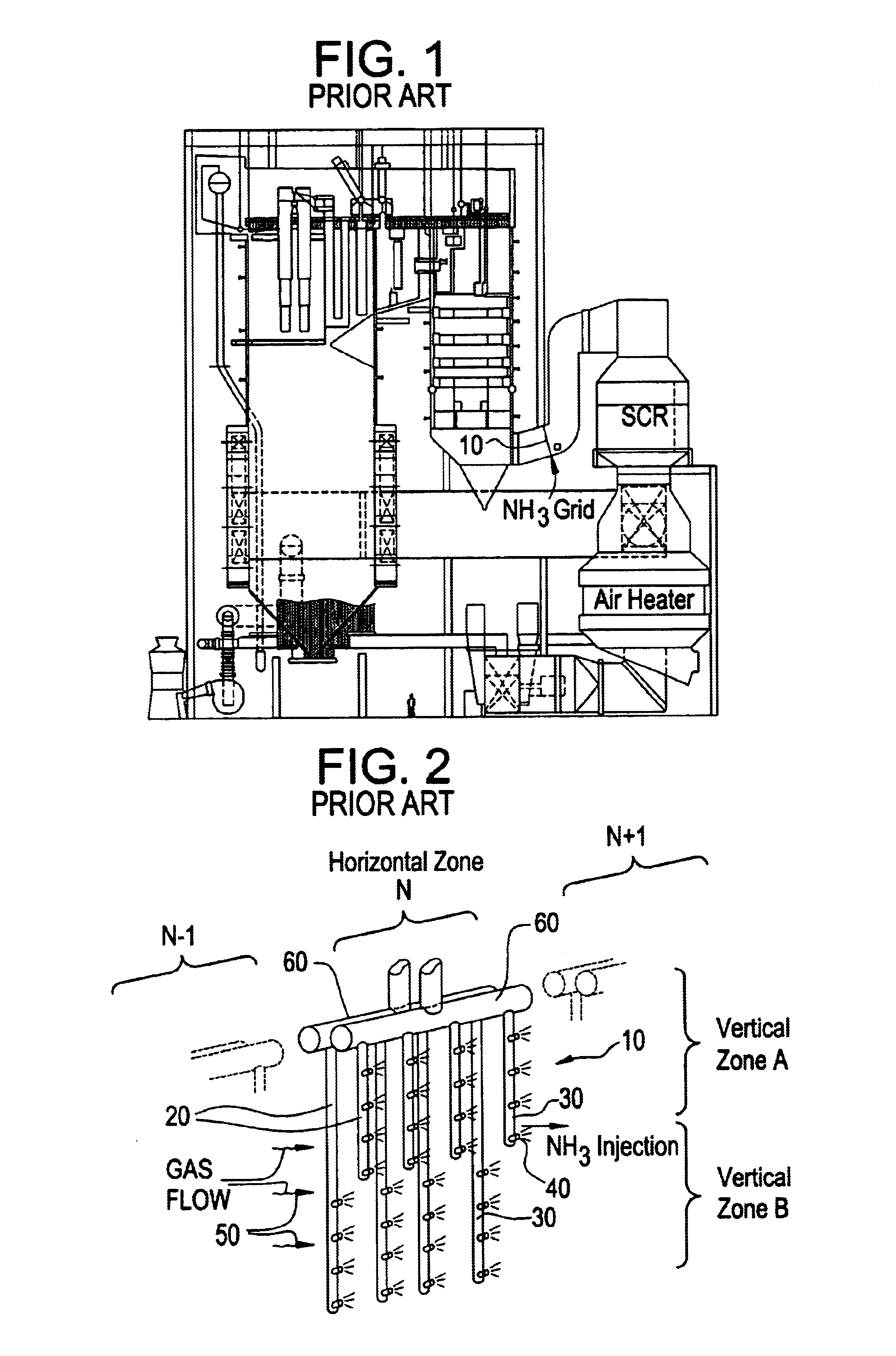
While the grid design 10 in FIG. 2 permits greater control over the dispersion of ammonia into the exhaust gas stream, it also results in blockage of a large area of the exhaust gas 50 flow path within the flue.
The blockage in turn results in a large flue gas side pressure drop between the furnace and stack (not shown).
This gas side pressure drop is undesirable because greater power consumption is needed for the fans to convey the flue gas through the installation, thereby adversely affecting the overall efficiency of the boiler system.

Method used


Image

  • Integrated air foil and ammonia injection grid for SCR systems
  • Integrated air foil and ammonia injection grid for SCR systems
  • Integrated air foil and ammonia injection grid for SCR systems

Examples


Embodiment Construction

[0025]Referring generally to the drawings, wherein like reference numerals designate the same or functionally similar elements throughout the several drawings, and to FIG. 4 in particular, there is shown a first embodiment of the integrated air foil and ammonia injection grid, generally designated 200, according to the present invention. The integrated air foil and ammonia injection grid according to the present invention is particularly suitable for injecting ammonia into flue gas streams conveyed within a flue and at a location upstream of an SCR system as described above. While the embodiments illustrated in FIGS. 4 and 5 show a vertical orientation of air foils comprising the invention, it will be understood by those skilled in the art that a horizontal orientation of the air foils could also be employed. It is also understood that the term “air foil” is used by way of example and not limitation; i.e., for the sake of convenience to generally describe the shape of such aerodynam...


PUM

PropertyMeasurementUnit
lengthaaaaaaaaaa
internal volumeaaaaaaaaaa
lengthsaaaaaaaaaa

Abstract

An integrated air foil and ammonia injection grid provides a plurality of air foils across a flue conveying flue gas. Each air foil has a leading curved edge and a tapered, pointed, trailing end. At least one injection pipe is positioned inside each air foil, and has at least one nozzle for injecting ammonia into the flue gas flowing across the air foils. Preferably, plural injection tubes are provided and positioned one behind the other in each air foil, and each injection tube in a given air foil has a length different than a length of the other injection tubes in the same air foil. A longest injection tube in a given air foil is located furthest downstream and proximate the tapered trailing edge and a shortest injection tube in the same air foil is located furthest upstream, remaining injection tubes in the same air foil being progressively shorter the further upstream any injection tube is located. Apertures may be provided on opposed lateral sides of the air foils for introducing a gas flow into the flue gas passing across the air foils. Ammonia flow to each injection pipe may be individually controlled.

Description

FIELD AND BACKGROUND OF THE INVENTION[0001]1. Field of the Invention[0002]The present invention relates generally to the field of utility and industrial boilers and furnaces and, in particular, to a new and useful integrated air foil and ammonia injection grid for use in a selective catalytic reduction (SCR) system which is used to reduce NOx emissions from such boilers and furnaces.[0003]2. Description of the Related Art[0004]NOx refers to the cumulative emissions of nitric oxide (NO), nitrogen dioxide (NO2) and trace quantities of other species generated during combustion. Combustion of any fossil fuel generates some level of NOx due to high temperatures and the availability of oxygen and nitrogen from both the air and fuel. Once the fuel has been selected, NOx emissions may be controlled using low NOx combustion technology and postcombustion techniques. One such postcombustion technique is selective catalytic reduction (SCR).[0005]SCR systems catalytically reduce flue gas NOx to ...

Claims


Application Information

Patent Timeline
Patent Type & Authority Patents(United States)
IPC IPC(8): B01F5/06B01F5/04B01D53/86
CPCB01D53/8631B01F5/0451B01F5/0456B01F5/061B01F5/0453B01F2005/0621B01F25/3132B01F25/31322B01F25/3131B01F25/4317B01F25/43171
Inventor ALBRECHT, MELVIN J.BOCK, MARK S.ROGERS, KEVIN J.MULL, JR., TED V.
Owner THE BABCOCK & WILCOX CO
Learn More