

Assist features for use in lithographic projection
a technology of assist features and lithographic projection, which is applied in the field of photolithographic masks, can solve problems such as imaging problems, and achieve the effect of better imaging
- Summary
- Abstract
- Description
- Claims
- Application Information
AI Technical Summary
Benefits of technology
Problems solved by technology
Method used
Image

Examples
embodiment 1
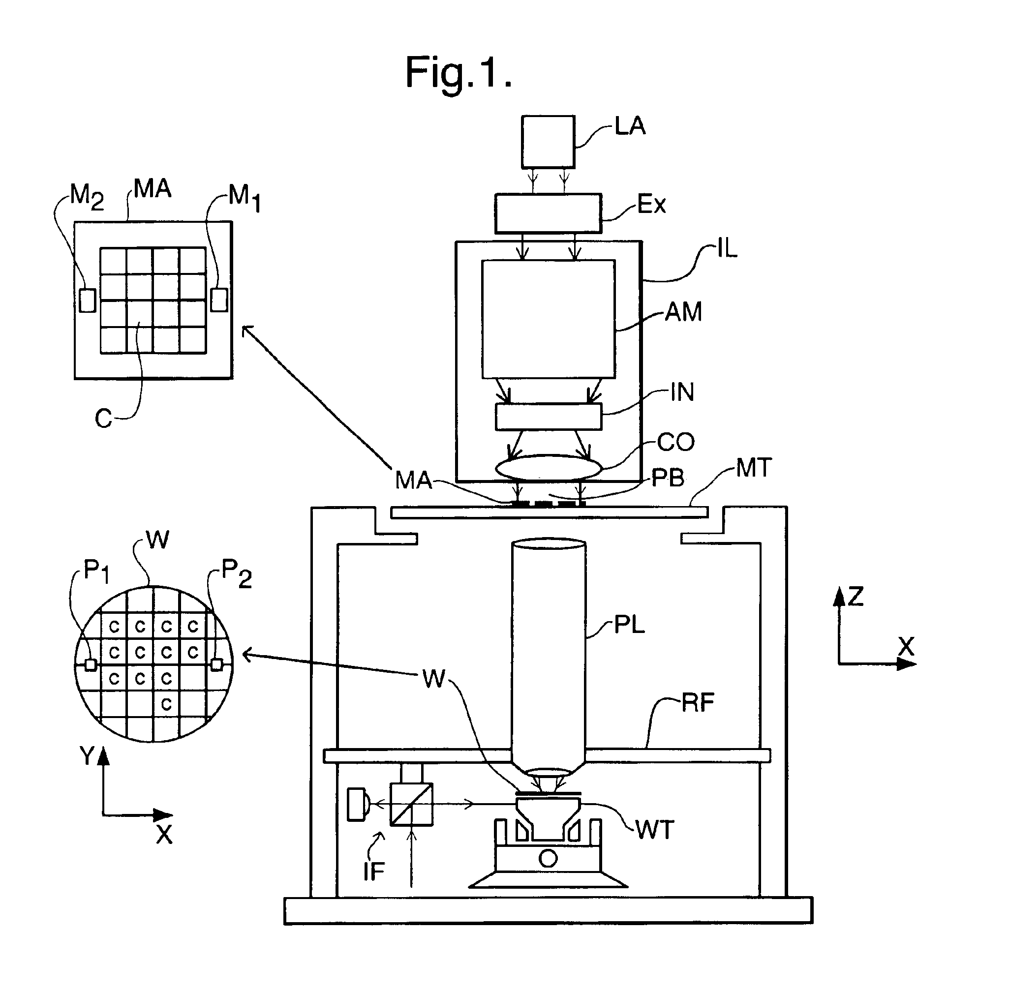
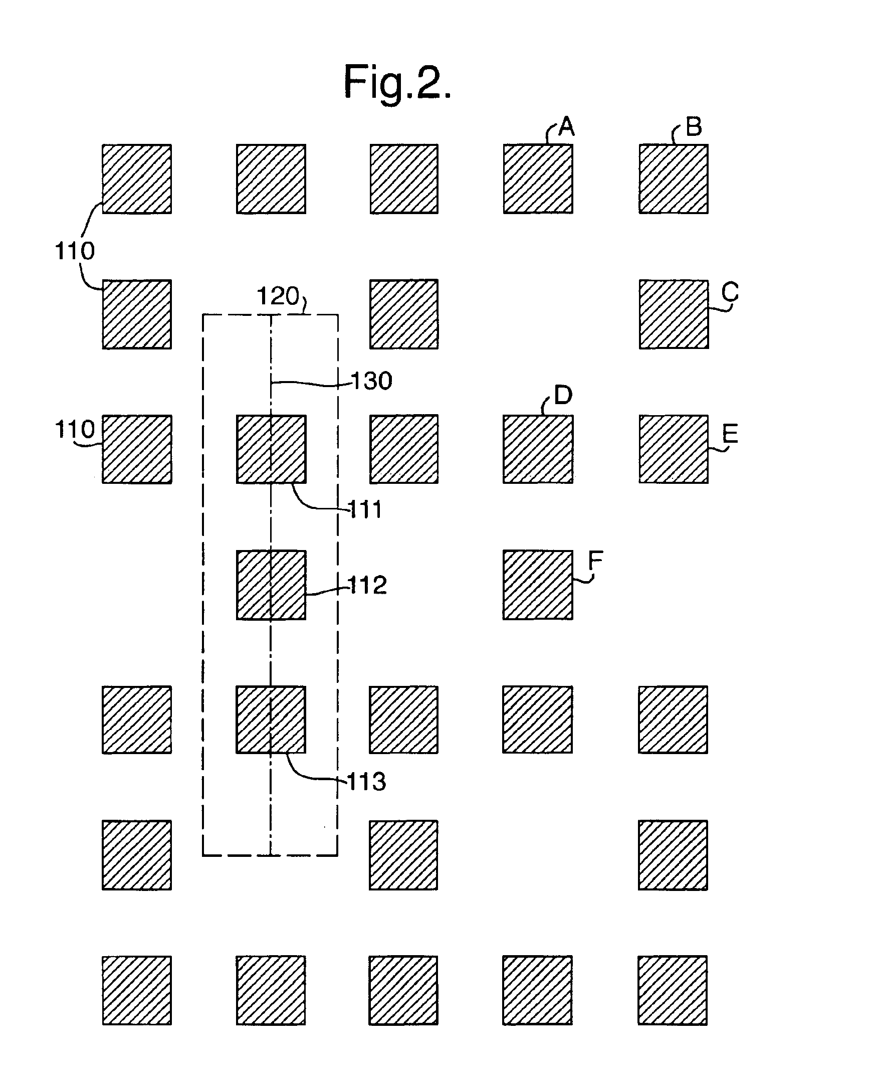
[0052]FIG. 2 shows part of a conventional 6% attenuated phase shift mask pattern which may be used in the lithographic projection apparatus described above for forming contact holes (vias) in a dynamic random access memory (DRAM) device. The mask pattern has an array of transparent areas 110, which let through the exposure radiation to expose the resist in the areas where contact holes are to be formed, in a substantially opaque field. It will be seen that the transparent areas are arranged such that a group of three, referenced 111, 112, 113, repeats regularly. The contact holes are 0.2 μm square with the spacing between contacts 0.2 μm. A reference area 120 of 0.4×1.6 μm2 is also shown.
[0053]The inventors have discovered that these contact holes do not image correctly, being misshapen and displaced from their nominal positions.
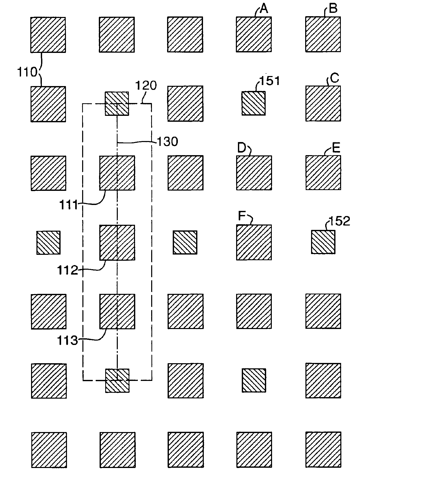
[0054]According to the present invention, assist features are added to the mask pattern to make the array of features more nearly symmetric. Suitable positi...
embodiment 2
[0063]FIG. 5 shows an alternative arrangement of contact holes 110. In this arrangement a pair of contact holes 211, 212 repeats to form a honeycomb structure. The contact holes may be 0.2 μm square with a spacing between adjacent contacts of 0.2 μm. Also shown is a reference area 220 of 0.4×0.9 μm2. According to the invention, the symmetry of this mask pattern is improved, as shown in FIG. 6, by adding an additional assist feature 251 at the center of each honeycomb cell. The assist features 251 may be square of side 0.12 μm, for example.
[0064]The improvement provided by the present invention in the second embodiment can be seen in FIG. 7 which is a graph of intensities of the aerial images produced by the mask patterns of FIGS. 5 and 6 along the line 230. As with FIG. 4, the solid line represents the intensity of the image produced by the mask pattern according to the invention (FIG. 6) and the dashed line that of the conventional pattern (FIG. 5). It will clearly be seen that the...
embodiment 3
[0065]FIG. 8 shows a conventional “brick wall” pattern of rectangles arranged in a staggered array. The rectangles are 0.2×0.5 μm2 with a spacing between adjacent rectangles of 0.2 μm. The reference area 320 is 0.6×0.6 μm2. As shown in FIG. 9, according to the invention, assist features 350 are placed between the rectangles 310. The assist features may again be 0.12 μm on each side, for example.
[0066]FIG. 10 is a contour plot at a 0.25 (arbitrary units) intensity threshold of the aerial image produced by the unit cell 320. The finely-dashed line represents the image produced by the present invention (FIG. 9) while the single-chain line represents that produced by the conventional mask pattern (FIG. 8). The double-chain line represents an ideal aerial image of the mask pattern with no 3 wave aberration. It will clearly be seen that the image provided by the present invention is closer to the ideal.
PUM
| Property | Measurement | Unit |
|---|---|---|
| wavelength | aaaaa | aaaaa |
| wavelength | aaaaa | aaaaa |
| wavelength | aaaaa | aaaaa |
Abstract
Description
Claims
Application Information