Photothermal power generation device and method

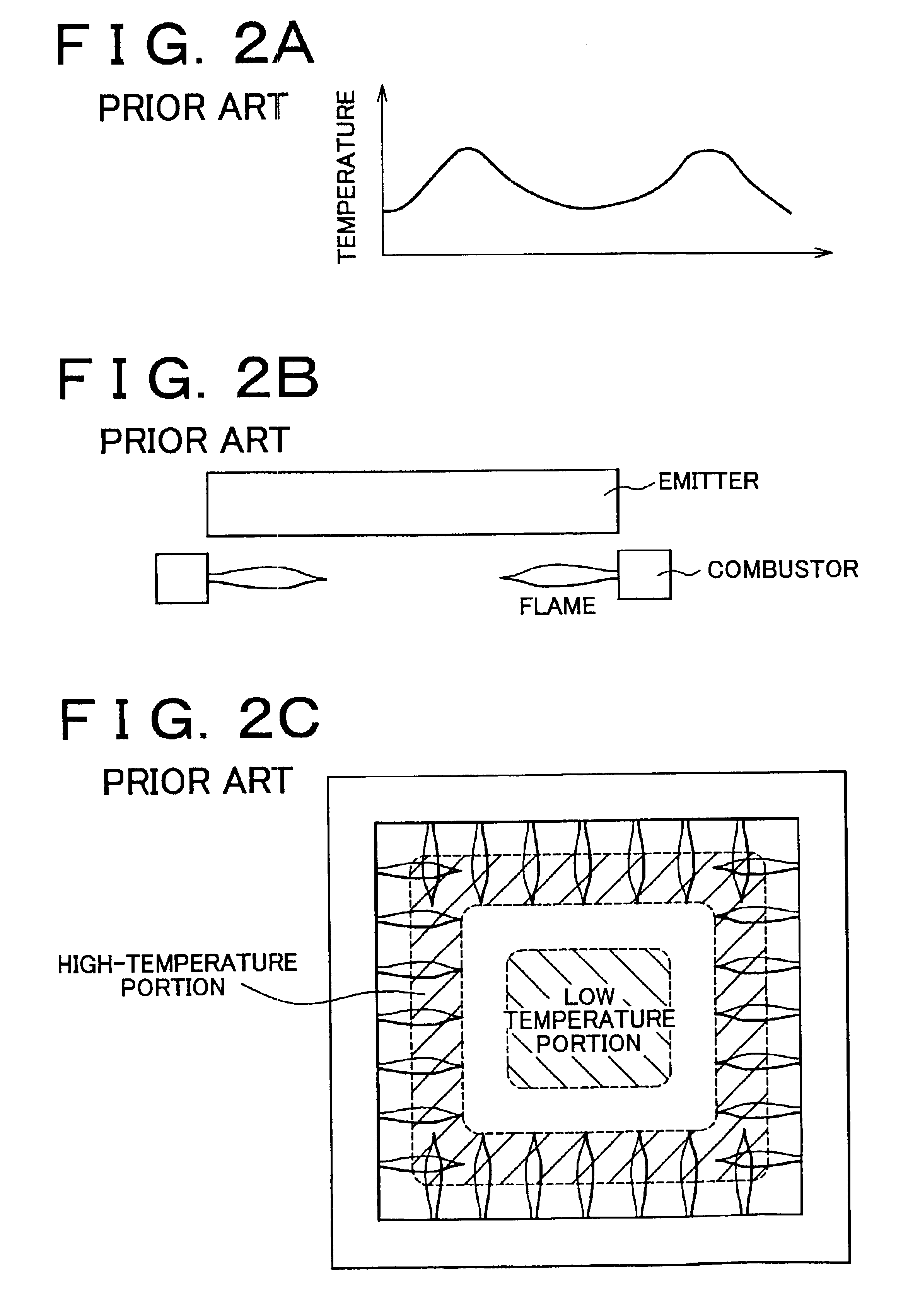
a power generation device and photothermal technology, applied in the direction of reciprocating combination engines, lighting and heating apparatuses, combustion types, etc., can solve the problems of power conversion efficiency drop, uneven dispersion uneven dispersion of rays of light emitted from the emitter, etc., to achieve uniform distribution of combustion gas in the emitter

Inactive Publication Date: 2005-05-03
TOYOTA JIDOSHA KK
View PDF26 Cites 5 Cited by
  • Summary
  • Abstract
  • Description
  • Claims
  • Application Information

AI Technical Summary

Benefits of technology

[0010]The invention has been made as a solution to the aforementioned problem. It is an object of the invention to provide a photothermal power generation device that achieves enhancement of the power generation efficiency by ensuring a uniform light-emitting intensity in an emitter.
[0014]The shape of flames changes depending on the shape or number of the fire vents formed in the combustor. In the photothermal power generation device constructed as described above, the fire vents are reduced in size or number to form long flames when low outputs are required, whereas the fire vents are increased in size or number to form flames of a suitable length when high outputs are required. By taking such a measure as an example, the combustion state in the combustor is controlled optimally in accordance with a required (target) output. As a result, the emitter can be heated uniformly as a whole.

Problems solved by technology

However, combustion gas is dispersed unevenly when flowing through the emitter.
This leads to uneven dispersion of rays of light emitted from the emitter.
Such uneven dispersion is attributable to inadequate distribution of flame-rising portions in the combustor, incompatibility with the flow resistance in the emitter, changes in operational circumstances (the state of passage of combustion gas through the emitter changes depending on how a combustion chamber changes in response to a change in required power generation amount), and the like.
As a result, a drop in power conversion efficiency occurs and causes a problem.

Method used


Image

  • Photothermal power generation device and method
  • Photothermal power generation device and method
  • Photothermal power generation device and method

Examples


Embodiment Construction

[0028]In the following description and the accompanying drawings, the invention will be described in more detail with reference to presently preferred embodiments.

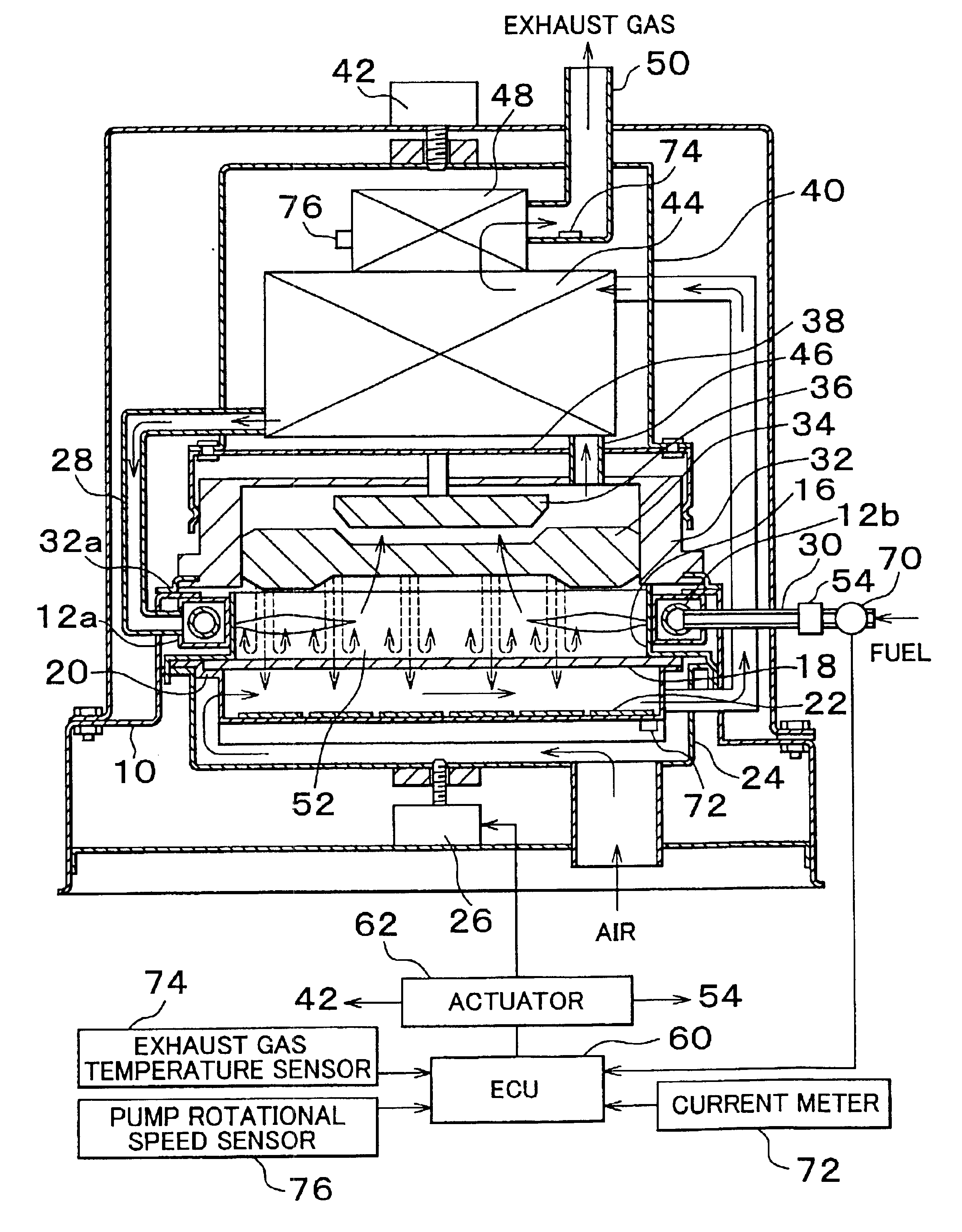
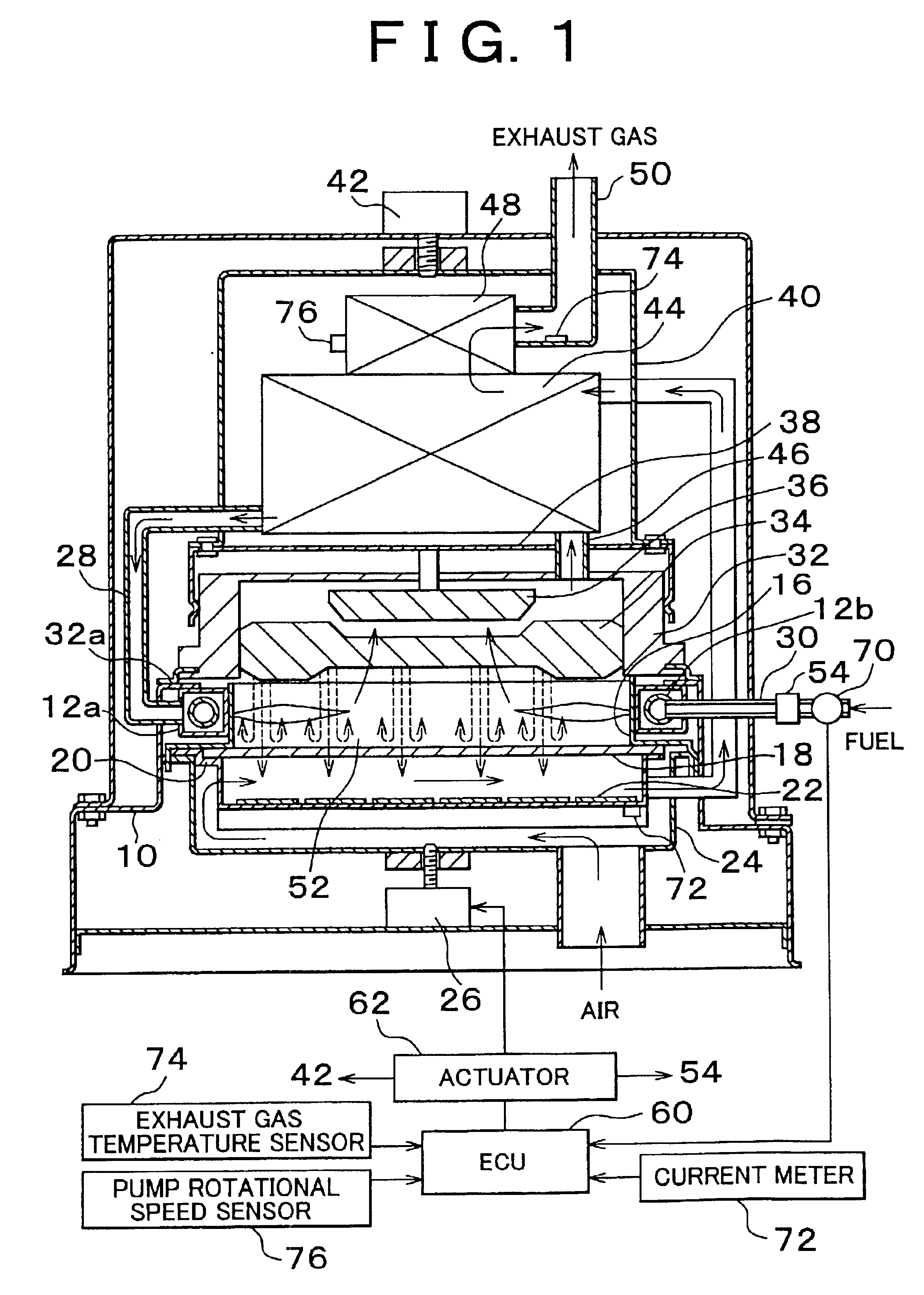
[0029]FIG. 1 is a cross-sectional view of the construction of a photothermal power generation device according to one embodiment of the invention. A base frame 10 is shown in FIG. 1. An air pipe 12a fixed to the base frame 10 by welding or the like and a fuel gas supply pipe 12b disposed inside the air pipe 12a are integrated with each other to constitute a combustor 12 (see FIGS. 5A and 5B). As is apparent from a detailed view of the combustor 12 shown in FIGS. 5A and 5B, a fuel gas blowout port 12c from which fuel gas is blown out is disposed in the fuel gas supply pipe 12b. Fire vents are disposed at predetermined intervals in the combustor 12. The mixture of fuel gas blown out from the fuel gas blowout port 12c and air supplied to the combustor 12 is blown out from the fire vents horizontally inwardly.

[0030]A plate 16 ...


PUM


Abstract

A photothermal power generation device designed to heat an emitter receives a supply of fuel and air, burns the fuel to produce combustion gas, and converts light emitted from the emitter into electric power by means of a photoelectric conversion element. The device is provided with a flow resistance adjusting unit for adjusting a flow resistance of the combustion gas in the emitter in accordance with a state of combustion gas, a combustor fire vent adjusting unit for adjusting the shapes of, or a number of, fire vents formed in the combustor in accordance with a required output, or a discharge state adjusting unit for adjusting a discharge state of exhaust gas in accordance with a state of the combustion gas. This photothermal power generation device provides uniform light-emitting intensity and enhances power generation efficiency.

Description

INCORPORATION BY REFERENCE[0001]The disclosure of Japanese Patent Application No. 2001-228133 filed on Jul. 27, 2001, including the specification, drawings, and abstract is incorporated herein by reference in its entirety.BACKGROUND OF THE INVENTION[0002]1. Field of the Invention[0003]The invention relates to a photothermal power generation device (TPV system) and method for generating power through thermophotovoltaic energy conversion for converting infrared rays (referred to as infrared radiation or heat rays as well) into electric power by means of a photoelectric conversion element (a photoelectric conversion cell).[0004]2. Description of the Related Art[0005]In a photothermal power generation device, an emitter is heated and emits infrared rays of a certain wavelength. The infrared rays impinge on a photoelectric conversion element and are converted into electric power. The photothermal power generation device has no movable portion and thus can realize a low level noise, low l...

Claims


Application Information

Patent Timeline
Patent Type & Authority Patents(United States)
IPC IPC(8): F23N3/08F23N3/00F23N3/02F23D14/12H01L27/14H01L31/04H01L31/042
CPCH02S10/30F23N3/08F23N3/02F23M2900/13004Y02E10/50
Inventor MURATA, KIYOHITONAKAYAMA, HIDEKI
Owner TOYOTA JIDOSHA KK
Why Eureka
Try Eureka