Phase locked loop circuit for reducing electromagnetic interference and control method thereof

Inactive Publication Date: 2005-05-03
SAMSUNG ELECTRONICS CO LTD
View PDF6 Cites 37 Cited by
  • Summary
  • Abstract
  • Description
  • Claims
  • Application Information

AI Technical Summary

Benefits of technology

[0008]The invention, also in part according to an embodiment of the invention, provides (in a phase-locked loop) a method of reducing electromagnetic interference caused by a clock signal produced by a voltage controlled oscillator, the method comprising: generating a control signal having a first type, e.g., sinusoidal, of slight variation in magnitude relative to a nominal magnitude value thereof; and providing the slightly varying control signal to a voltage-controlled oscillator (“VCO”) to obtain a clock signal exhibiting a second type, e.g., sinusoidal, of slight variation in frequency relative to a nominal frequency value thereof.
[0009]The invention, also in part according to an

Problems solved by technology

Electromagnetic interference (EMI), which is harmful to the human body, is generated by the harmonic components.
However, there are limitations on reducing EMI in a system by shielding or using capacitance.
However, each of the spread spectrum clock signal generators using the Sigma Delta modulation method or the frequency modulation meth

Method used


Image

  • Phase locked loop circuit for reducing electromagnetic interference and control method thereof
  • Phase locked loop circuit for reducing electromagnetic interference and control method thereof
  • Phase locked loop circuit for reducing electromagnetic interference and control method thereof

Examples


Example

[0020]Hereinafter, the present invention will be described in detail with reference to the accompanying drawings.

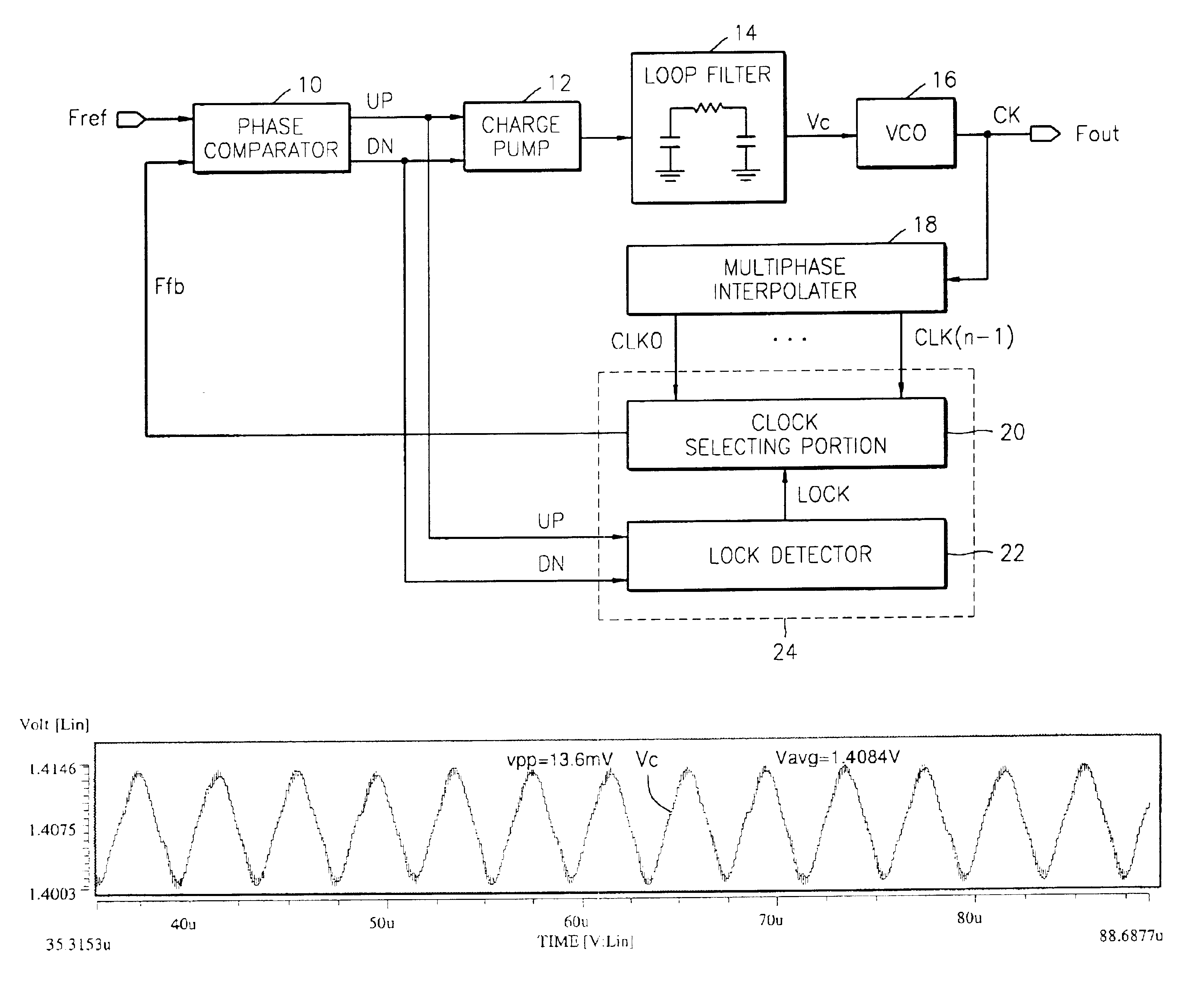
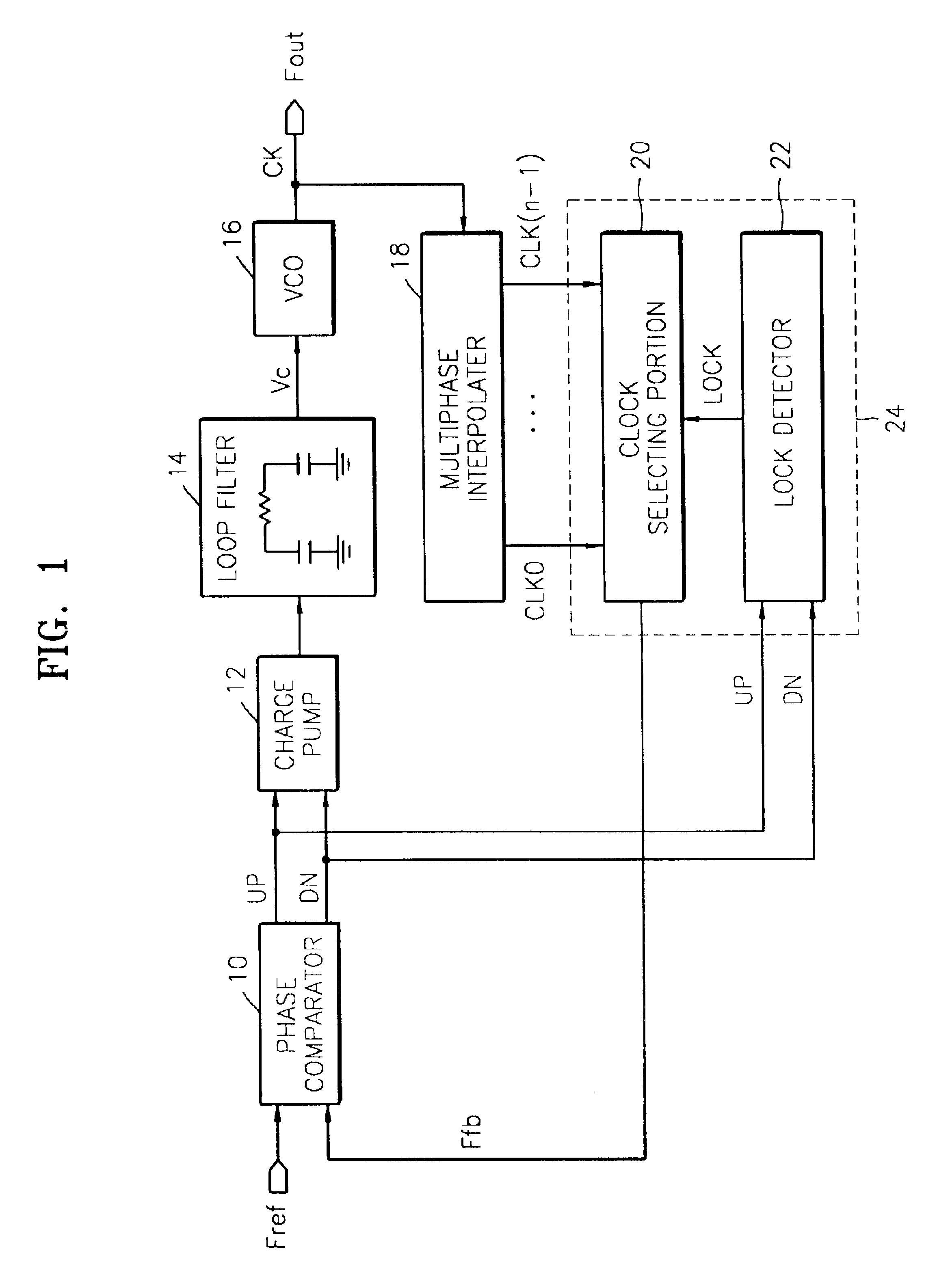
[0021]FIG. 1 is a block diagram schematically illustrating a preferred embodiment of a phase locked loop (PLL) for reducing wideband electromagnetic interference (EMI) according to the present invention. The PLL circuit for reducing wideband EMI includes a phase comparator 10, a charge pump 12, a loop filter 14, a voltage-controlled oscillator (VCO) 16, a multiphase interpolater 18, and a feedback clock outputting portion 24.

[0022]Referring to FIG. 1, the phase comparator 10 compares the phase of a reference clock signal Fref with the phase of a feedback clock signal Ffb output from the feedback clock outputting portion 24 and outputs the compared result as an up / down signal UP / DN. The charge pump 12 generates a charge signal for supplying charges to the loop filter 14 or sinking charges from the loop filter 14 in response to the up / down signal UP / DN.

[0023]The loop filter...


PUM


Abstract

For a phase-locked loop, disclosed is a method (and corresponding apparatus) for reducing electromagnetic interference caused by a clock signal produced by a voltage controlled oscillator, the method comprising: generating a control signal having a first type, e.g., sinusoidal, of slight variation in magnitude relative to a nominal magnitude value thereof; and providing the slightly varying control signal to a voltage-controlled oscillator (“VCO”) to obtain a clock signal exhibiting a second type, e.g., sinusoidal, of slight variation in frequency relative to a nominal frequency value thereof. The slight variation is non-negligible.

Description

FIELD OF THE INVENTION[0001]The present invention relates to a phase locked loop (PLL) circuit, and more particularly, to a PLL circuit for reducing electromagnetic interference (EMI) in a high speed system and a control method thereof.BACKGROUND OF THE INVENTION[0002]Computer speeds continue to become faster. A fast clock signal is required for fast data processing. Harmonic components are exhibited by a high speed clock signal. Electromagnetic interference (EMI), which is harmful to the human body, is generated by the harmonic components. EMI in a system has been reduced by shielding or using capacitance. However, there are limitations on reducing EMI in a system by shielding or using capacitance.[0003]Most of the EMI in a computer system is generated in a clock generating portion that generates the high speed clock signal. In other words, EMI is generated in a high speed clock signal due to harmonics. Recently, techniques for reducing EMI by lowering the energy level of harmonics...

Claims


Application Information

Patent Timeline
IPC IPC(8): H03L7/081H03L7/099H03L7/08
CPCH03L7/0996H03L7/081H03L7/08
Inventor KIM, SANG-YOUNGJUN, PIL-JAE
Owner SAMSUNG ELECTRONICS CO LTD
Why Eureka
Try Eureka