Isolation transformers

a transformer and isolation technology, applied in the field of isolation transformers, can solve problems such as errors and damages, various inconveniences and/or accidents, and the protection of electronic devices and equipment that contain densely packed circuits from noise-related troubles, and achieve the effects of high noise attenuation rates, high reliability, and sufficient suppression of noise amplitudes

Inactive Publication Date: 2005-05-03
K K DENKEN SEIKI INST
View PDF17 Cites 18 Cited by
  • Summary
  • Abstract
  • Description
  • Claims
  • Application Information

AI Technical Summary

Benefits of technology

[0015]The issue to be resolved by the present invention is to provide isolation transformers with high noise attenuation rates as well as high reliability by sufficiently suppressing the amplitudes of noise attenuation characteristic curves, which are irregular, saw-tooth shaped waves with crests and troughs of various sizes, of multi-layer, multi-winding transformers.

Problems solved by technology

However, integrated circuits are controlled by extremely small electric energy, and therefore, are subject to errors and damages caused by some noise transmitted from external sources.
Such events will eventually lead to various inconveniences and / or accidents owing to malfunctioning or stopping of various equipment and devices that contain integrated circuits and of systems using them.
Consequently, protection of electronic devices and equipment that contain densely packed and complicated circuits from noise-related troubles have become an urgent issue.
Components with extremely complicated combinations such as multi-layer, multi-winding coils in transformers thus have random and complicated noise attenuation characteristics; as the crests have extremely low attenuation, this scheme cannot provide highly reliable isolation transformers.
However, it has been impossible for the isolation transformers of electromagnetic-shield type to satisfy this condition.
Therefore, being effectively attenuated by the resistivity of the short-circuit ring, it is hard for the high-frequency components to flow from the primary coil to the secondary coil.
However, as evidently shown in FIG. 11, the suppression of amplitudes of the characteristic curve for the attenuation rate of normal-mode noise with irregular saw-tooth shaped waves with crests and troughs of various sizes in the high-frequency region above a few MHz is not sufficient yet.

Method used


Image

  • Isolation transformers
  • Isolation transformers
  • Isolation transformers

Examples


Embodiment Construction

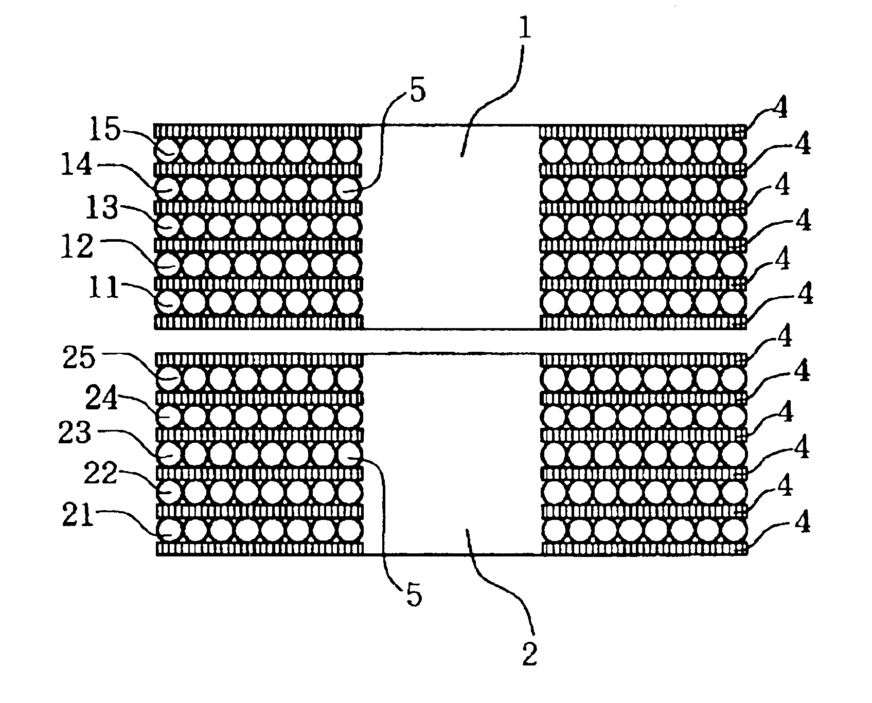
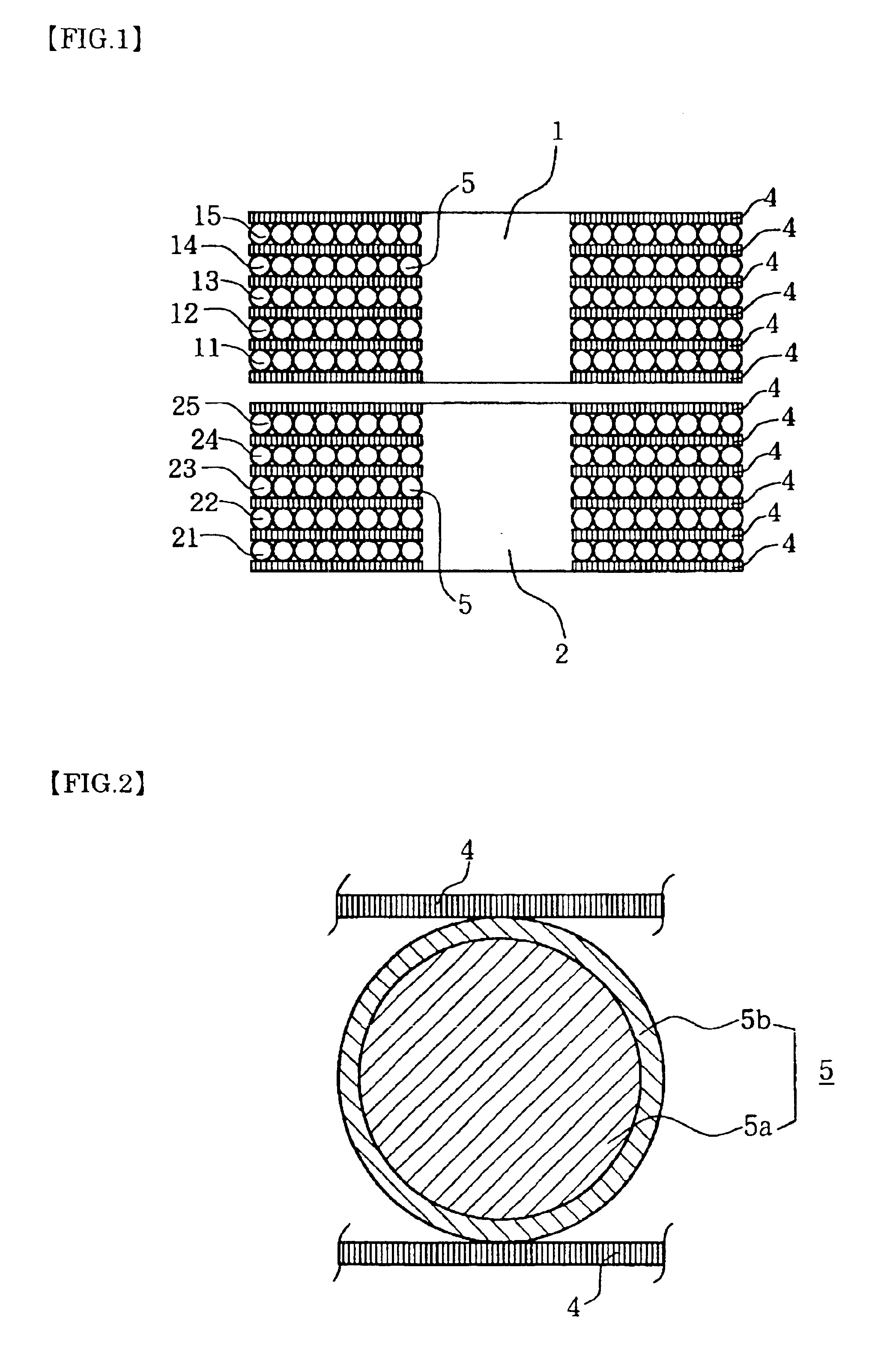
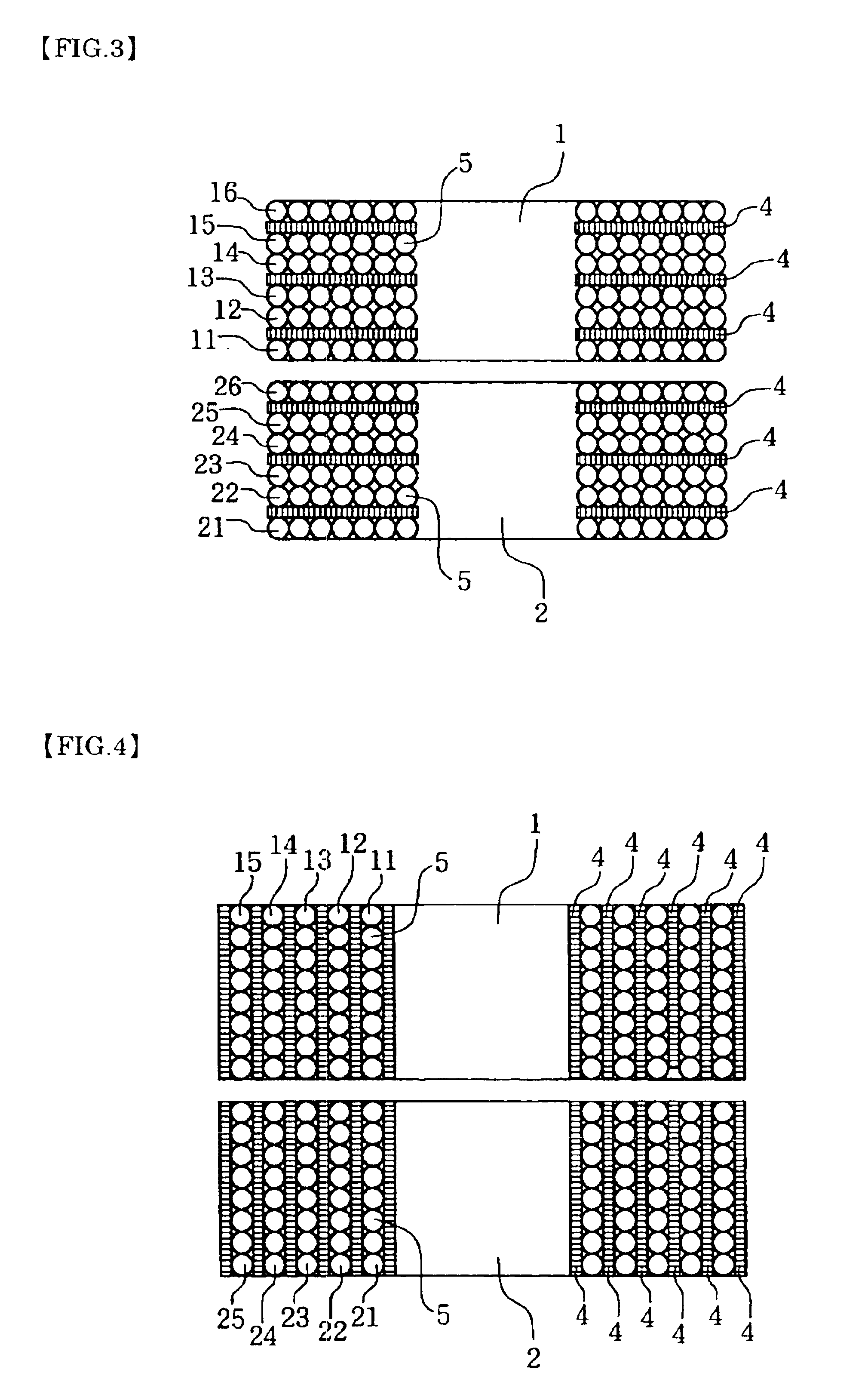
[0043]FIG. 1 depicts a cross section of an isolation transformer of the short-circuit-ring type, which is the first embodiment of the present invention with its bobbin and core omitted and with much reduced numbers of windings and layers for easier comprehension. FIG. 2 depicts a magnified part of FIG. 1. The primary coil is a ring-type coil, in which an insulated, covered, copper-wire 5 was wound with many (N1) layers and many (MI) windings. Likewise, the secondary coil is also a ring-type coil, in which an insulated, covered, copper-wire 5 was wound with many (N2) layers and many (M2) windings. The insulated, covered, copper-wire 5 is a general one with an insulated cover 5b such as enamel placed over a copper-wire 5a.

[0044]For example, a transformer with output 10VA for fundamental wave with voltage 22V has 156 as M1, 166 as M2 as well as 13 as N1 and 14 as N2, respectively.

[0045]As shown in FIG. 6, the core that forms a magnetic path between the primary coil 1 and the secondary...


PUM

PropertyMeasurementUnit
frequencyaaaaaaaaaa
frequencyaaaaaaaaaa
thicknessaaaaaaaaaa

Abstract

The issue to be resolved by the present invention is to provide isolation transformers with high noise attenuation rates as well as high reliability, in the high-frequency region above a few MHz, by sufficiently suppressing the amplitudes of noise attenuation characteristic curves, which are irregular, saw-tooth shaped waves with crests and troughs of various sizes, of multi-layer, multi-winding transformers.
An isolation transformer comprised by a multi-layer, multi-winding primary coil 1, a multi-layer, multi-winding secondary coil 2, and a core that forms a magnetic path between the aforementioned primary coil and the aforementioned secondary coil, functions as an isolation transformer to resolve the aforementioned issue by changing the coil layers of one or both of the coils formed by winding an insulated, covered, copper-wire 5 to a multi-layer, multi-winding coil, into which a number of short-circuit rings 4 made of conducting films are inserted and layered.
The planer configuration of the aforementioned conducting short-circuit rings 4 is made approximately identical to that of the neighboring coil-layers, and their thickness is made approximately identical to or less than the skin depth of the induced current generated by the skin effect in the high-frequency region, in which resonances should be suppressed.

Description

BACKGROUND OF THE INVENTION[0001]This invention is related to isolation transformers that suppress high-frequency electromagnetic noise (hereafter called noise) transmitted through power transmission lines and / or signal transmission lines.[0002]Micro-computers are being used in various fields such as information, communication, and other industries in addition to daily life etc. This is due to down-sizing, lower prices, and higher reliability of micro-computers driven by the continuous advancement of integrated circuits. However, integrated circuits are controlled by extremely small electric energy, and therefore, are subject to errors and damages caused by some noise transmitted from external sources. Such events will eventually lead to various inconveniences and / or accidents owing to malfunctioning or stopping of various equipment and devices that contain integrated circuits and of systems using them. Consequently, protection of electronic devices and equipment that contain densel...

Claims


Application Information

Patent Timeline
Patent Type & Authority Patents(United States)
IPC IPC(8): H01F27/28H01F27/34H01F27/36H01F17/04H01F27/32H01F30/00
CPCH01F27/2885H01F27/362H01F2019/085H01F27/36H01F27/363H01F27/32
Inventor YAGASAKI, AKIHIKO
Owner K K DENKEN SEIKI INST
Why Eureka
Try Eureka