A/D converter with reduced power consumption

a converter and power consumption technology, applied in the field of a/d converters and systems, can solve the problems of large power consumption, increased power consumption at high frequency may have to be accepted as an unavoidable cost, and the cost of power consumption at lower frequency, so as to reduce power consumption in the comparator, shorten the time period during which the through current flows are relatively short, and reduce the effect of power consumption

Inactive Publication Date: 2005-05-03
FUJITSU LTD
View PDF13 Cites 9 Cited by
  • Summary
  • Abstract
  • Description
  • Claims
  • Application Information

AI Technical Summary

Benefits of technology

[0022]In the invention described above, the first period that is the analog sample period is different in duration from the second period that is the comparison period, thereby reducing the analog sample period to shorten a time length during which a through current flows th...

Problems solved by technology

If a configuration is made such as to be operable at high frequency, it will give rise to a problem in that the through electric current described above increases, resulting in large power consumption.
An increase in po...

Method used


Image

  • A/D converter with reduced power consumption
  • A/D converter with reduced power consumption
  • A/D converter with reduced power consumption

Examples


Embodiment Construction

[0032]In the following, embodiments of the present invention will be described with reference to the accompanying drawings.

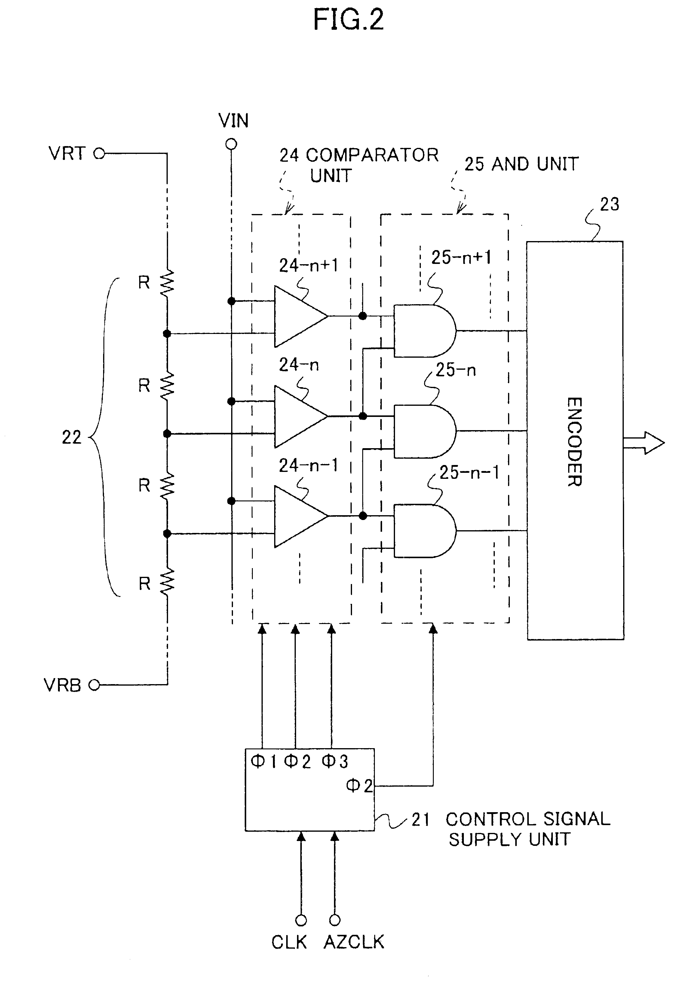
[0033]FIG. 2 is a circuit diagram showing a configuration of a parallel-type A / D converter according to the present invention.

[0034]The A / D converter of FIG. 2 includes a control signal supply unit 21, a potential divider circuit 22, an encoder 23, a comparator unit 24, and an AND unit 25. The potential divider circuit 22 includes a series of resistors R for dividing the potential between a potential VRT and a potential VRB. Divided potentials obtained at joint points between resistors are supplied to the comparator unit 24 as reference potentials.

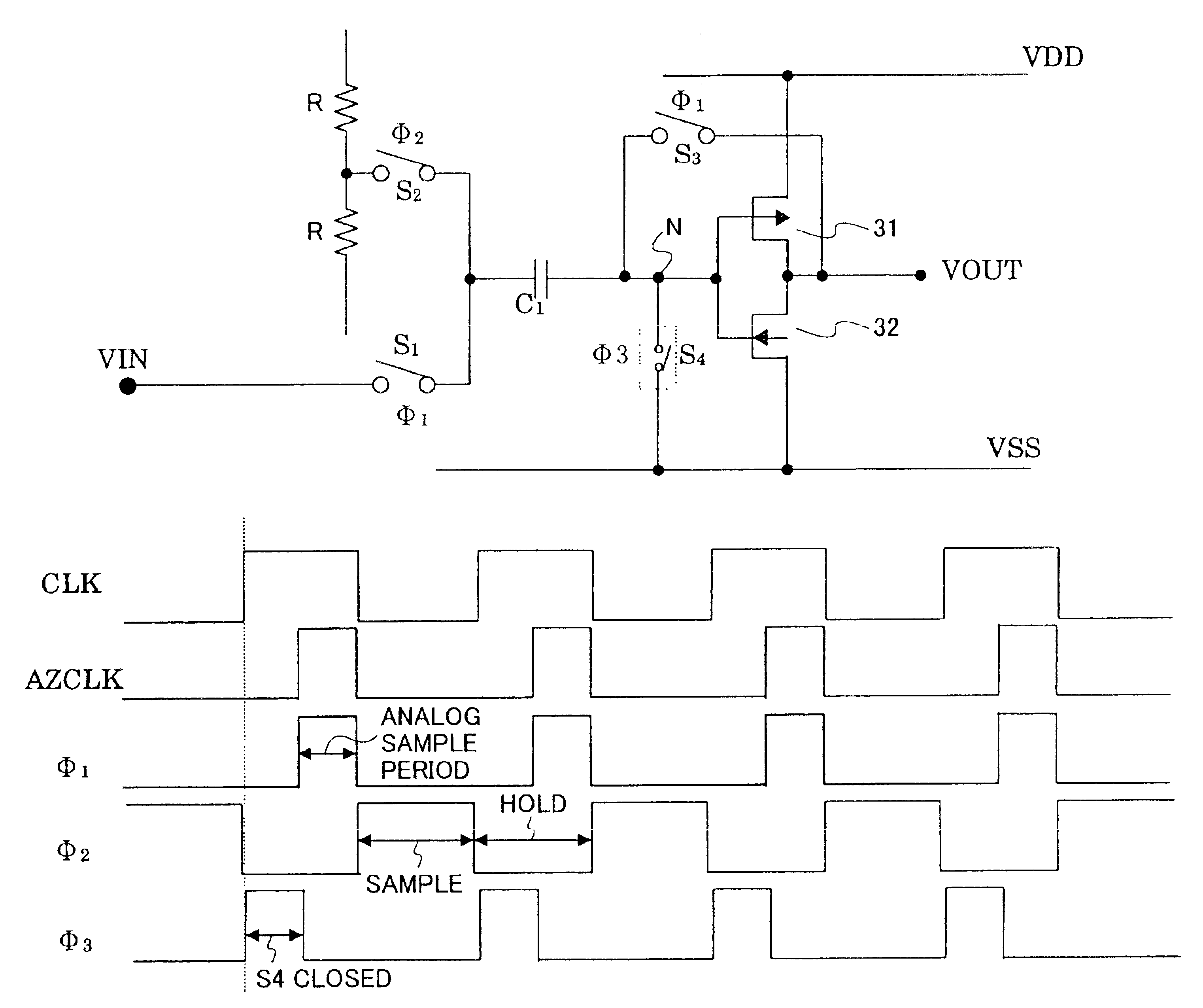
[0035]The comparator unit 24 includes a plurality of comparators (only 24-n−1, 24-n, and 24-n+1 are shown in FIG. 2) where each comparator receives a corresponding one of the reference voltages from the potential divider circuit 22. Each comparator operates based on the control signals Φ1 through Φ3 supplied form the c...


PUM


Abstract

An A/D converter includes a plurality of comparators, each of which samples an analog input potential during a first period, and compares the analog input potential with a reference potential during a second period, an encoder which encodes comparison results obtained by the comparators, and a control signal supply unit which generates one or more control signals that define the first period and the second period such as to make a duration of the first period different from a duration of the send period, and supplies the one or more control signals to the plurality of comparators.

Description

BACKGROUND OF THE INVENTION[0001]1. Field of the Invention[0002]The present invention generally relates to A / D converters and systems having A / D (analog-to-digital) converters, and particularly relates to a parallel-type A / D converter and a system having such a parallel-type A / D converter.[0003]2. Description of the Related Art[0004]A parallel-type A / D converter of an 8-bit configuration, for example, includes 255 converters, each of which receives respective reference potentials obtained by a resister-based potential divider. These 255 converters compare the respective reference potentials with an input potential, thereby converting the input potential into a digital value.[0005]FIG. 1 is a circuit diagram showing a configuration of a comparator used in a parallel-type A / D converter.[0006]The comparator of FIG. 1 includes a PMOS transistor 11, an NMOS transistor 12, a buffer 13, an inverter 14, switches S1 through S3, and a condenser C1. The buffer 13 and the inverter 14 generate c...

Claims


Application Information

Patent Timeline
IPC IPC(8): H03K5/24H03K5/22H03M1/00H03M1/36H03K5/08
CPCH03K5/249H03M1/002H03M1/36
Inventor TAKAKUSAGI, HIROSHIMIZUGUCHI, TOSHITAKATSUCHIYA, CHIKARAYAMAMOTO, KATSUYOSI
Owner FUJITSU LTD
Why Eureka
Try Eureka