Single-mode fiber systems

Active Publication Date: 2005-05-03
FURAKAWA ELECTRIC NORTH AMERICA INC
View PDF4 Cites 13 Cited by
  • Summary
  • Abstract
  • Description
  • Claims
  • Application Information

AI Technical Summary

Benefits of technology

[0015]Other considerations may dictate hybrid systems in which juncture is at a different power level—e.g., at lower power level (than the usually-prescribed TSMF launch power) to take advantage of other ESMF at

Problems solved by technology

Use of ESMF in claimed systems is expected to meet requirements for the desired twenty-year or greater lifetime between media upgrades—of particular consequence in high-population a

Method used


Image

  • Single-mode fiber systems
  • Single-mode fiber systems
  • Single-mode fiber systems

Examples


Embodiment Construction

General

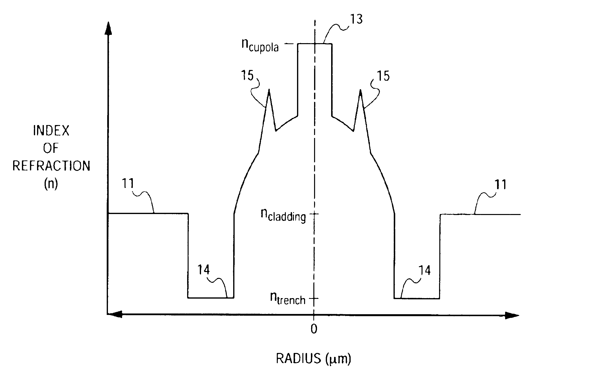
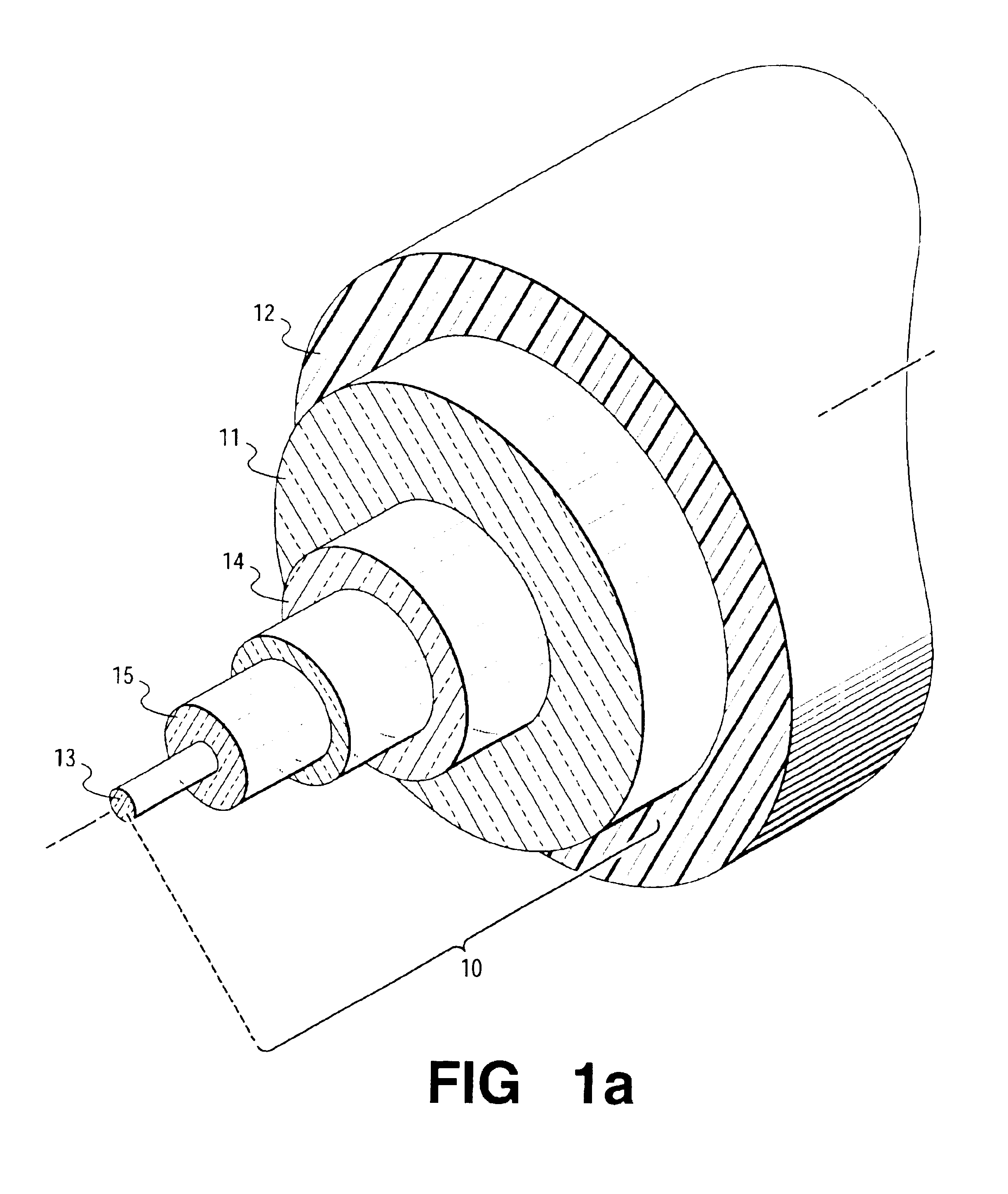
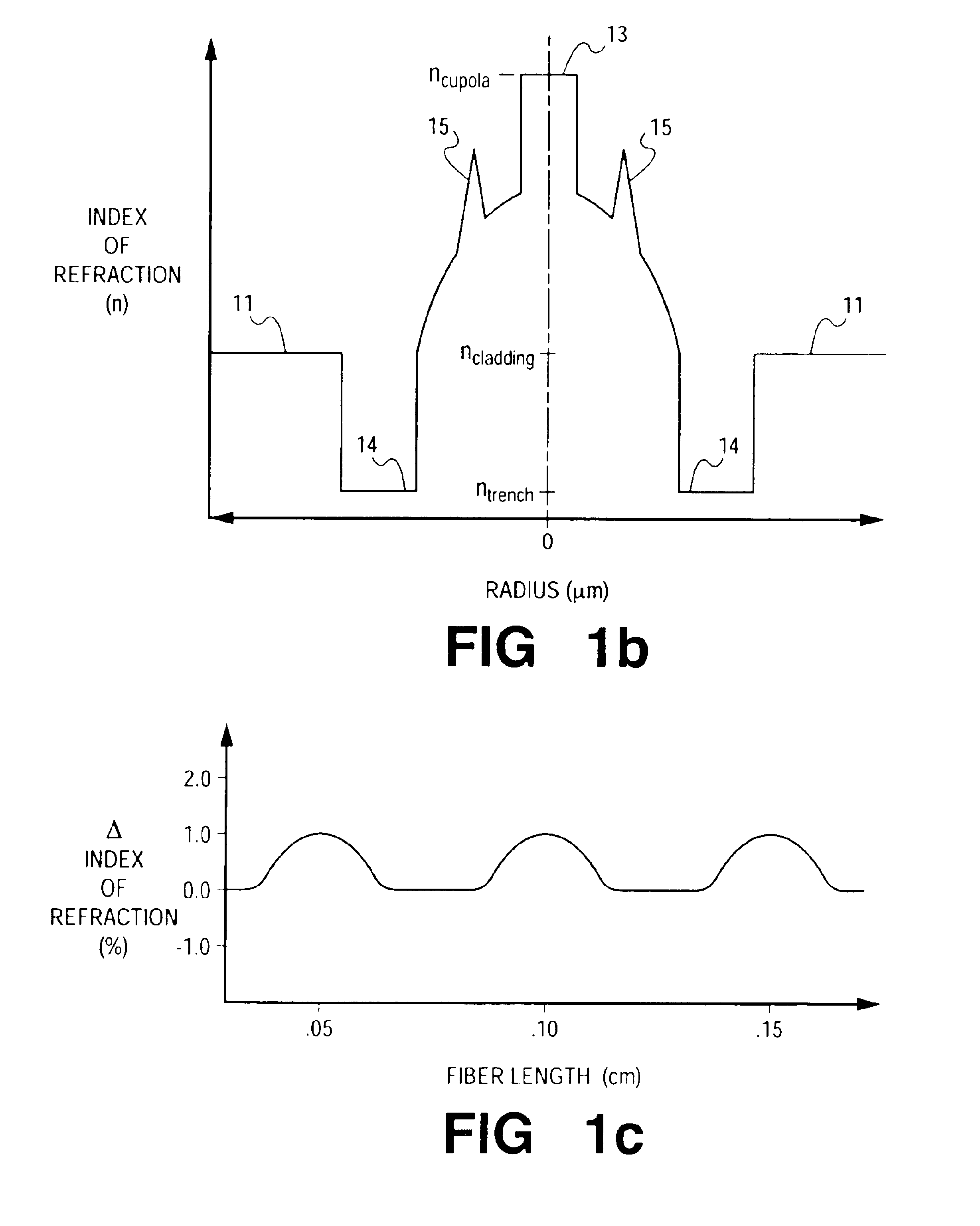
[0063]Claims are directed to optical fiber communication systems making substantial use of ESMF of co-pending patent application Ser. No. 10 / 407,376 “Optical Fiber For Single-Mode Operation”. While reference should be made to that application for detailed description of the entire category of contemplated fiber structures, brief description of representative ESMF structures is useful here. FIGS. 1a-1c are referred to in that description.

[0064]Unless otherwise indicated, discussion contemplates a system of wavelength operating range including λ0=1550 nm. It is likely significant commercial systems will, in the future, continue to operate within this high transparency 1550 nm “window”—including the range, 1480-1580 nm—with expanded operation over 1400-1675 nm, particularly as enabled with ESMF. Properties of ESMF are generally to be compared with those of Traditional Single-Mode Fiber (TSMF). For these purposes, TSMF is to be considered state-of-the-art single-mode fiber. As pr...


PUM


Abstract

Single-mode optical fiber systems, incorporating fiber of core radius of sufficient size to support the fundamental mode together with from one to three higher order modes, exhibit performance/cost advantages relative to systems based on traditional single-mode fiber.

Description

FIELD OF THE INVENTION[0001]Optical fiber systems based on single-mode fiber.BACKGROUND OF THE INVENTION[0002]Commonly used optical fiber is: silica-based; of outside dimension ˜125 microns (μm); with “up-doped” core; and often undoped cladding. Initially introduced multimode fiber, with its core size of 25-50 μm, now occupies but a niche position—that of short and intermediate distance communications with operation at the nominal system wavelength of 850 μm. At this time, longer-distance communications is based on single-mode fiber—structure of the same outside diameter, but now of reduced core size. Single-mode fiber, with its 1-6 μm radius core, is designed to support solely the first or “fundamental” mode. Higher-order modes, not present in the initially-launched laser pulse, but yielded, e.g., by encounter with unintended scattering centers, are not supported in such core structures, and, accordingly, are ultimately radiated from the fiber. (Content of such spurious higher-orde...

Claims


Application Information

Patent Timeline
IPC IPC(8): G02B6/036G02B6/02
CPCG02B6/02252G02B6/03666G02B6/02047G02B6/03627G02B6/0283
Inventor WHITE, IAN A.
Owner FURAKAWA ELECTRIC NORTH AMERICA INC
Why Eureka
Try Eureka