Distributed control system and an associated system component for the distributed control system

a distributed control system and control system technology, applied in the direction of programme control, electric controllers, total factory control, etc., can solve the problems of manual data entry, unreliable and simple option, and the inability to assign unique identifiers to individual system components on the display screen, so as to ensure data consistency and improve reliability. the effect of reliability

Inactive Publication Date: 2005-05-03
SIEMENS AG
View PDF12 Cites 0 Cited by
  • Summary
  • Abstract
  • Description
  • Claims
  • Application Information

AI Technical Summary

Benefits of technology

[0010]It is an advantage of the invention that the transmission of the position of the individual system components as component-specific data (which represent the spatial coordinates) provides a unique identification of the system components in that these data act as identifiers. It is not possible to assign identical component specific data to two different system components since the spatial coordinates always differ. This results in an improved reliability during configuration of the system components. Since the spatial coordinates of the system components are transmitted to the configuration unit via the communications channel, manual multiple data entry is eliminated, and thus, data consistency is ensured. The component-specific data, which uniquely identifies the corresponding system component, permits, in a simple manner, an automatic assignment of unique addresses in the configuration unit.
[0011]If the system components are equipped with a unit for automatically determining their positions, in particular with a GPS (Global Positioning System) receiver, no operator is involved in determining the spatial coordinates at all. In other words, the potential for erroneous manual data entry is completely eliminated. In cases where the costs of equipping the system components with such a device are prohibitive, the system components can be provided, in an inexpensive manner, with a device for entering their positions. In this case, the data can be manually entered or by data transmission via an interface. Advantageously, the spatial coordinates of the positions of the system coordinates are automatically determined by a portable device, which can, again, include a GPS receiver.
[0012]Advantageously, the configuration unit is provided with a layout plan generator, which generates a layout plan, preferably in the form of a piping and installation diagram, and which contains information on the spatial positions of the system components. If, in addition, the configuration unit is configured to assign and to transmit a unique physical address on the communications channel to a system component whose position was previously received by the configuration unit in the form of the component specific data, the unique identification of the system components through their spatial coordinates can advantageously be used for assigning the unique addresses. Thus, it is not necessary to program or to set the addresses in the individual components or in the configuration unit. To code the addresses thus generated by the configuration unit, smaller data volumes than those for coding the spatial positions are sufficient. Thus, shorter addresses can be advantageously used for communications during the subsequent operation of the system.

Problems solved by technology

A technically simple but costly and unreliable option is to program the system components individually and to generate, separately therefrom, a layout plan by means of the configuration unit.
A drawback of this option is that the programming of the individual system components is relatively costly.
The drawback is that affixing the adhesive labels to the paper layout plan and assigning the unique identifiers to the individual system components on the display screen must be done manually.
Therefore, this method is subject to errors.

Method used


Image

  • Distributed control system and an associated system component for the distributed control system
  • Distributed control system and an associated system component for the distributed control system

Examples


Embodiment Construction

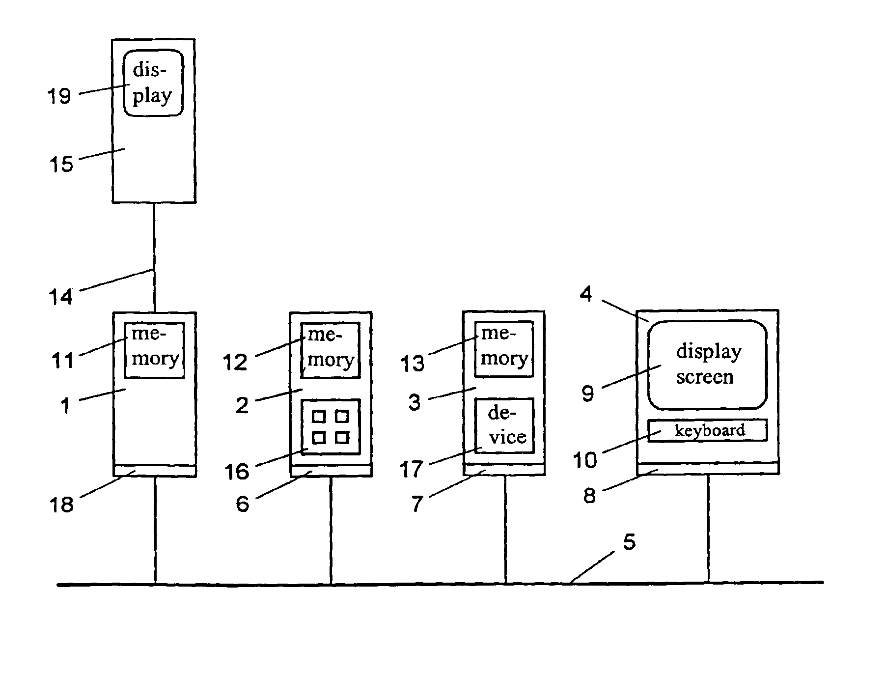
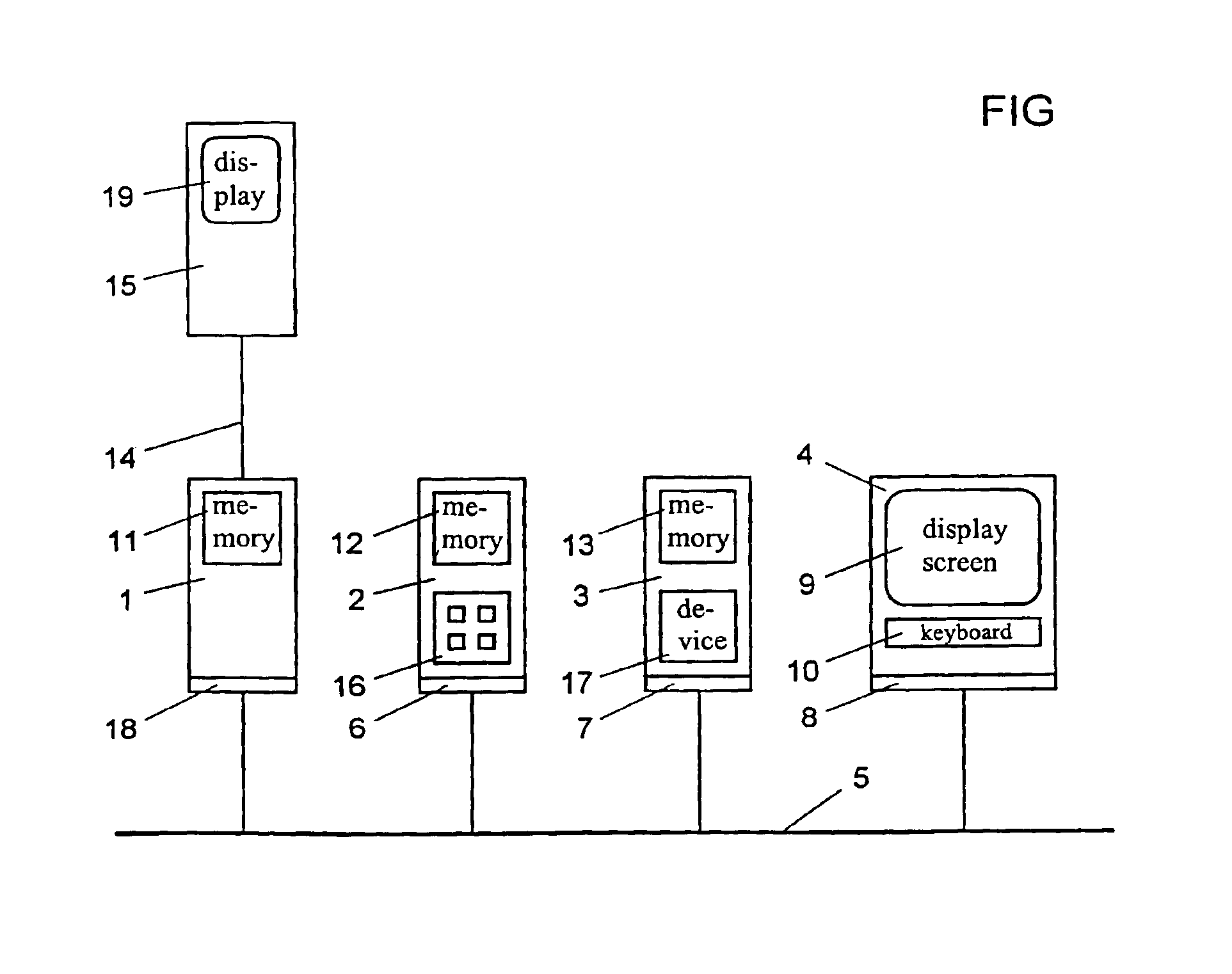
[0014]The FIGURE shows a distributed control system having system components 1, 2 and 3 and a configuration unit 4, which are interconnected by a bus 5. The bus 5 is configured as a communications channel for data transmission purposes. For communication purposes, the system components 1, 2, 3 and the configuration unit 4 have respective communications devices 18, 6, 7 and 8. The system components 1, 2 and 3 are, for instance, an actual value sensor, a controller, and an actuator, respectively. The configuration unit 4 configures the communication between the individual components. Therein, the configuration unit can be implemented by a powerful personal computer, on which, as a software tool, a suitable program is installed for generating a piping and installation diagram in the form of a layout plan. The layout plan includes information on the function and the spatial position of the components within the system. Preferably, the layout plan is displayed on a display screen 9 of th...


PUM


Abstract

A distributed control system having system components (1, 2, 3). The positions of the system components (1, 2, 3) are stored in respective memories (11, 12, 13) as component-specific data, which represent the spatial coordinates of the positions. The system components (1, 2, 3) transmit their respective positions to a configuration unit (4) via a communications channel (5). By means of a layout plan, e.g., in the form of a piping and installation diagram, the component-specific data of the individual system components (1, 2, 3) is assigned to the configured system components. In addition, a respective physical address is assigned to each of the system components (1, 2, 3). This achieves simple and reliable configuration of the system components (1, 2, 3). The distributed control system is used, in particular, in process apparatuses.

Description

[0001]This is a Continuation of International Application PCT / DE99 / 03956, with an international filing date of Dec. 10, 1999, which was published under PCT Article 21(2) in German, and the complete disclosure of which is incorporated into this application by reference.FIELD OF AND BACKGROUND OF THE INVENTION[0002]The present invention relates to a distributed control system, in particular for implementing an automation system. Furthermore, the present invention relates to a system component for such a distributed control system.[0003]German Patent DE 196 24 929 A1 discloses a distributed control system, in which sensors and actuators are connected to a configuration unit via a bus system. Therein, the bus system is configured as a communications channel. In the configuration unit, an operating and monitoring interface is generated. In this reference, several possibilities for configuring and operating the distributed control system are described. A technically simple but costly and ...

Claims


Application Information

Patent Timeline
Patent Type & Authority Patents(United States)
IPC IPC(8): G05B19/418
CPCG05B19/418Y02P90/02
Inventor HEIDEL, ROLANDDOEBRICH, UDO
Owner SIEMENS AG
Why Eureka
Try Eureka