
Apparatus for processing continuously fed elongate material

a technology of elongated material and apparatus, which is applied in the direction of wrapping, wrapping, transit packaging, etc., can solve the problems of limiting throughput speed, requiring film feed to be slowed or stopped, and similar problems with other types of known sealing mechanisms, so as to increase the throughput of processed materials

Inactive Publication Date: 2005-05-10
CMD CORP
View PDF24 Cites 12 Cited by
  • Summary
  • Abstract
  • Description
  • Claims
  • Application Information

AI Technical Summary

Benefits of technology

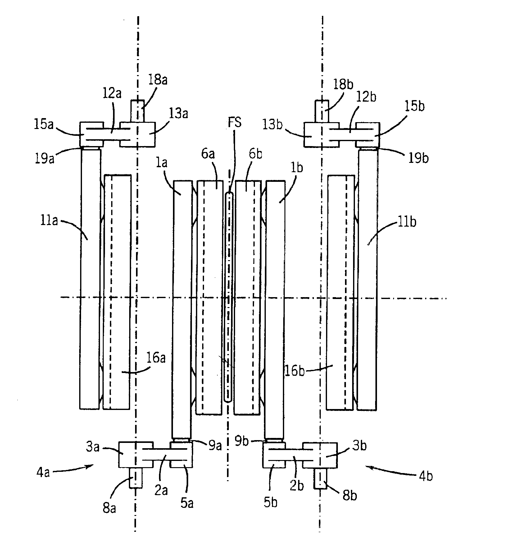
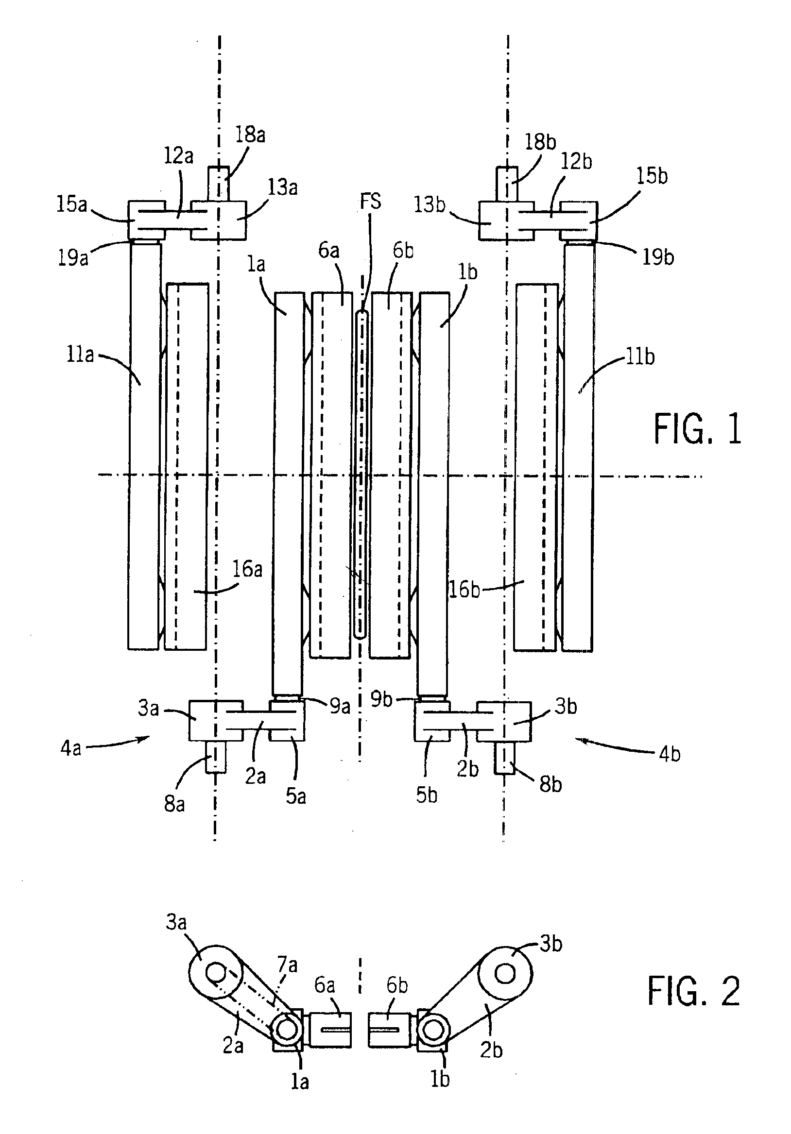
[0017]The cantilevered tool arrangement substantially frees up space in the processing area. Thus, and further according to the invention, a second pair of similarly driven tools may be provided to perform the same or a different function in opposition to the first pair. The second pair of tools is similarly supported in cantilevered fashion, but from tool drives located adjacent a second (opposite) edge of the processing path.
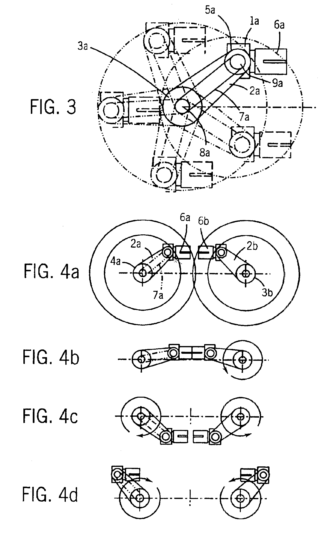
[0021]It is advantageous to have independent control of the tool drives. When the tool is withdrawn from the processed material, independent control makes it possible to shorten the cycle time significantly by more rapid tool repositioning upstream to the next contact point on the material, allowing an increase in throughput. Independent control also provides flexibility in adjusting tool motion, and in the case of dual pairs of tools insures that unwanted tool interference will not occur.

Problems solved by technology

The paddle wheel-type sealing mechanism significantly limits throughput speed because of the required contact (sealing) time of the sealing jaws, and because return of the sealing jaws upstream to the start position requires more time than the filling of a bag, thus requiring the film feed to be slowed or stopped.
Similar problems exist with other types of known sealing mechanisms.

Method used


Image

  • Apparatus for processing continuously fed elongate material
  • Apparatus for processing continuously fed elongate material
  • Apparatus for processing continuously fed elongate material

Examples


Embodiment Construction

[0028]Referring to FIGS. 1 and 2, a first pair of sealing tools 6a, 6b are shown which have just parted contact with the opposite faces of a film tube FS. Tube FS is shown in sectional end view in FIG. 1, moving away from the viewer and into the plane of the figure. Tools 6a, 6b are resiliently mounted on tool carriers 1a, 1b, respectively, as explained in more detail below. Tool carriers 1a, 1b are cantilevered from tool drives 4a, 4b, respectively, located adjacent one edge of the processing path along which tube FS moves, such that the tools 6a, 6b extend perpendicularly and on opposite sides of the processing path.

[0029]Tool drive 4a comprises a hollow crank arm 2a rigidly connected to or formed with shaft 3a at its drive end, and having an integrally formed head 5a at its free end. A stub shaft 9a is rigidly attached to tool carrier 1a and is journaled in head 5a for pivoting movement relative to crank arm 2a about a tool carrier axis. Shaft 3a is journaled on fixed shaft 8a fo...


PUM

PropertyMeasurementUnit
anglesaaaaaaaaaa
linear speedaaaaaaaaaa
timeaaaaaaaaaa

Abstract

Apparatus for processing continuously fed elongate material, such as forming sealed bags from continuously fed film tubes, uses at least one pair of orbital tools that are cantilevered from tool drives (e.g., crank arms) at one edge of the material, extending transversely across the direction of material travel to engage opposite faces of the material. During material engagement the tools run synchronously with the moving material, but may be returned upstream rapidly to reengage the material for the next processing cycle. In order to achieve a higher throughput an additional pair of tools can be used, cantilevered and driven from the opposite edge of the material, maintaining the same processing (e.g., sealing) time. Through this arrangement the tools on opposing sides can alternate contact with the material and be run independently of each other.

Description

RELATED APPLICATIONS[0001]This is a continuation of, and claims the benefit of the filing date of, U.S. patent application Ser. No. 10 / 279,512, filed on Oct. 23, 2002, entitled Apparatus For Processing Continuously Fed Elongated Material, which is a continuation of U.S. patent application Ser. No. 09 / 458,694, filed on Dec. 13, 1999 now abandoned, entitled Apparatus For Processing Continuously Fed Elongated Material, now abandoned.TECHNICAL FIELD[0002]The invention relates to apparatus for the processing of continuously fed material with tools which act on the material intermittently. Such apparatus is used, for example, in the production of filled bags made from an elongate film tube which is welded or glued at discrete locations to form the ends of the bags and seal in their contents. The film material typically is made of a thermoplastic foil which can be sealed by the application of pressure and heat or adhesive.BACKGROUND ART[0003]Depending on bag length, tools (e.g., sealing ja...

Claims


Application Information

Patent Timeline
Patent Type & Authority Patents(United States)
IPC IPC(8): B65B51/26B65B51/30
CPCB65B51/306B29C66/1122B29C66/83543B29C66/4312B29C66/849B29C65/48B29C66/43129B29C65/02B29C66/43B29C66/83513
Inventor HELWIG, CHRISTIANMATHEYKA, THOMAS
Owner CMD CORP
Learn More