Fluid filled unit formation machine and process

Active Publication Date: 2005-05-10
AUTOMATED PACKAGING SYST
View PDF24 Cites 78 Cited by
  • Summary
  • Abstract
  • Description
  • Claims
  • Application Information

AI Technical Summary

Benefits of technology

[0005]The machine and process of the present invention provide enhanced production of dunnage units similar to those produced by the systems of the Lerner Patent and Applications but at greatly improved production rates. Unlike those systems, the machine and process of the present invention are also capable of producing liquid filled units. Specifically, a novel and improved unit formation machine is disclosed. The machine includes a rotatable drum having a spaced pair of cylindrically contoured surfaces. An elongated nozzl

Problems solved by technology

The system of the Lerner Patent and Applica

Method used


Image

  • Fluid filled unit formation machine and process
  • Fluid filled unit formation machine and process
  • Fluid filled unit formation machine and process

Examples


Embodiment Construction

[0022]While the following description describes a dunnage formation system, it should be recognized the preferred embodiment of the machine is sterilizable so that beverages such as water and fruit juice may be packaged using the novel web, machine and process.

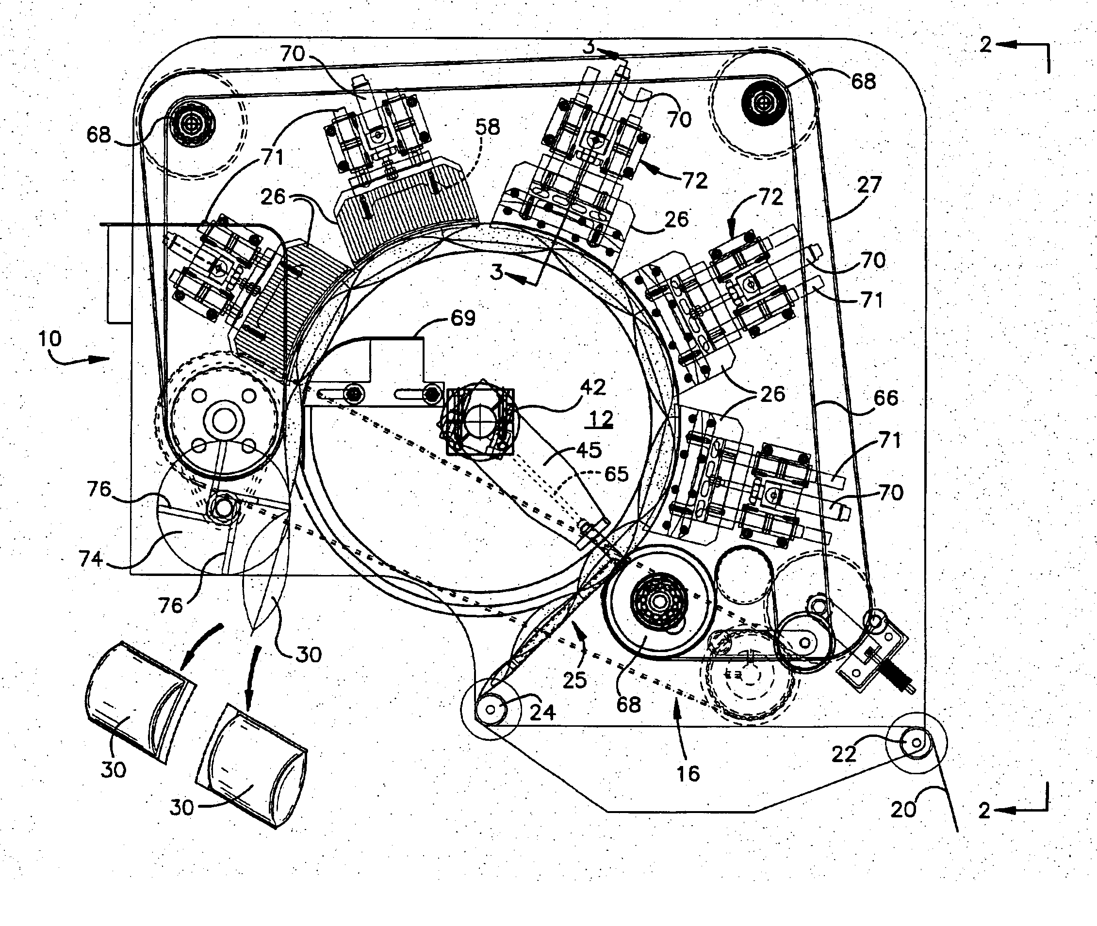
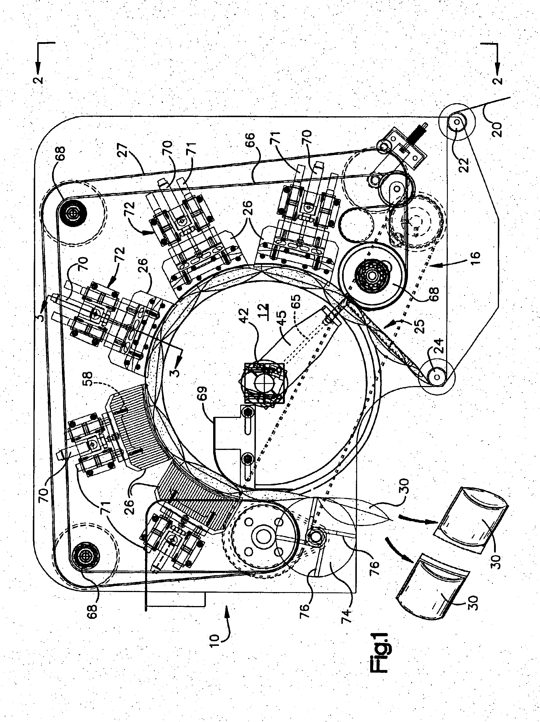
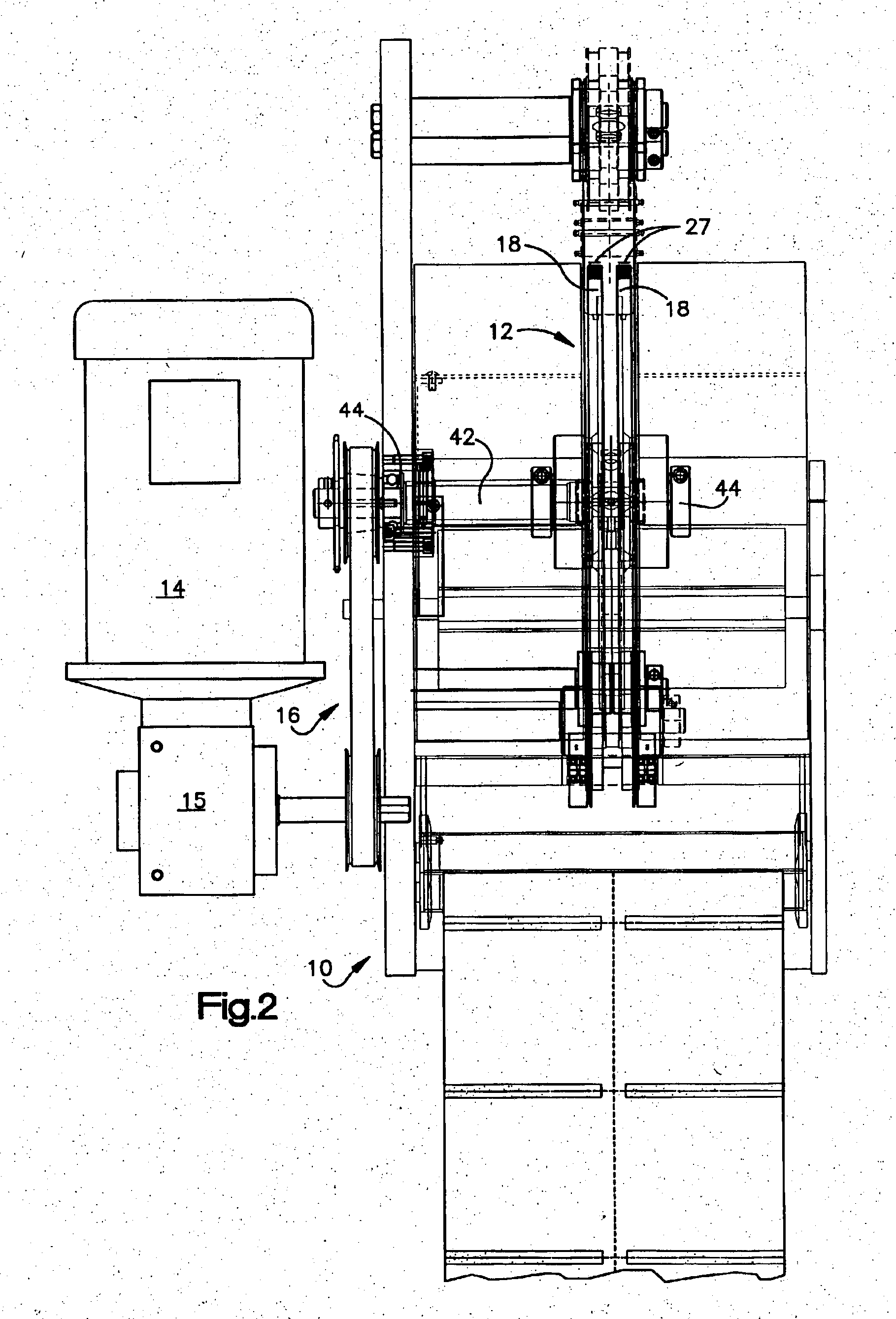
[0023]Referring now to the drawings and FIGS. 1 and 2 in particular, a dunnage formation machine is shown generally at 10. The machine includes a rotatable drum 12 which is driven by a motor 14 via a gear box 15 and a belt and pulley arrangement 16, FIG. 2. In the preferred and disclose arrangement, the drum is comprised of spaced annular disks 18.

[0024]When the machine is in use a web 20 is fed from a supply, not shown. As is best seen in FIG. 1, the web 20 passes over a guide roll 22 and thence under a guide roll 24 to an inflation station 25. The web 20 is fed around the disks 18 to pass under, in the disclose embodiment, three heat shoes 26 which shoes heat metal transport belts 27 to seal layers of the web. The heat softe...


PUM

PropertyMeasurementUnit
Pressureaaaaaaaaaa

Abstract

A machine for the manufacture of inflated plastic dunnage and other fluid filled units is disclosed. In a disclosed and pictured dunnage embodiment, the machine includes a hollow shaft rotatably mounted on a frame. In the preferred embodiment the shaft is solid. With either embodiment a drive is operably connected to the shaft for causing the shaft to rotate about its axis and a drum mounted on the shaft to rotate with the shaft. The drum is in the form of a pair of closely spaced discs having perimetral, cylindrically contoured sealing surfaces for support and, in cooperation with driven metal belts, transport of a web being formed into dunnage units. Sets of heating and cooling shoes having spaced arcuate surfaces are complementally positioned adjacent the drum surfaces with the cooling shoes downstream from the heating shoes in the direction of dunnage formation rotation. A nozzle is mounted generally tangentially of the drum at a location midway between the discs. Each of the cooling shoes includes an air expansion chamber communicating through a shoe inlet when in use with a supply of air under pressure. In the hollow shaft embodiment one cooling shoe chamber has an outlet in communication with the nozzle via the shaft.

Description

[0001]This invention relates to a novel machine and process for producing dunnage and other fluid filled units with a novel web.BACKGROUND OF THE INVENTION[0002]U.S. Re Pat. No. 36,501 reissued Jan. 18, 2000 and U.S. Re Pat. No. 36,759 reissued Jul. 4, 2000 respectively entitled “Method for Producing Inflated Dunnage” and “Inflated Dunnage and Method for its Production” and based on original patents respectively issued Sep. 3, 1996 and Dec. 2, 1997 to Gregory A. Hoover et al. (the Hoover Patents) disclose a method for producing dunnage utilizing preopened bags on a roll. The preopened bags utilized in the Hoover patents are of a type disclose in U.S. Pat. No. 3,254,828 issued Jun. 2, 1966 to Hershey Lerner and entitled “Flexible Container Strips” (the Autobag Patent). The preferred bags of the Hoover patents are unique in that the so called tack of outer bag surfaces is greater than the tack of the inner surfaces to facilitate bag opening while producing dunnage units which stick to...

Claims


Application Information

Patent Timeline
IPC IPC(8): B31D5/00B29C35/16B29C49/00B29C49/58B29C65/00B29C65/18B29C65/74
CPCB29C65/18B29C66/0342B29C66/232B29C66/439B29C66/81457B29C66/81465B29C66/8161B29C66/83421B29C66/83511B31D5/0073B65D75/42B65D75/527B65D81/052B29C49/58B29C65/305B29C66/4312B29C66/81427B29C66/8181B29C66/83433B29C49/0047Y10T156/1084B29C65/745B29C66/1122B29C66/43B29C66/81423B29C2035/1658B29C2049/6027B29C2049/6036B29C2793/0045B29C2793/0081B29C2793/009B29K2023/06B29L2022/02B29L2031/7138B29L2031/737B31D2205/0052Y10T156/1712Y10T156/1062Y10T156/12Y10T156/1056B29C65/00B29C66/71B29C49/0691
Inventor LERNER, HERSHEYLIEBHART, DANA
Owner AUTOMATED PACKAGING SYST
Why Eureka
Try Eureka