
Sandwich-molded guide for transmission device

Inactive Publication Date: 2005-05-10
TSUBAKIMOTO CHAIN CO +2
View PDF19 Cites 29 Cited by
  • Summary
  • Abstract
  • Description
  • Claims
  • Application Information

AI Technical Summary

Benefits of technology

[0013]Another object of the invention is to provide a guide which can easily be injection-molded without using a complex mold and complex manufacturing steps, and which has not only enhanced mechanical strength but also good sliding contact properties and good wear resistance.
[0014]Still another object of the invention is to provide a molded guide for a transmission device, which is light in weight and which has enhanced durability.
[0022]The sandwich-molding process of this invention is a process of manufacturing a molded product consisting of two kinds of polymeric materials, a so-called “two-layered” molded product, by injection-molding two kinds of molten polymeric materials into a mold, whose shape corresponds to the external shape of the product to be molded. The two polymeric materials are molded simultaneously or substantially simultaneously. A known injection-molding machine for sandwich molding can be used in the sandwich-molding process according to the invention. Although known injection-molding machines for sandwich molding include various sandwich nozzles, in the case of an injection-molding machine for sandwich molding including parallel type sandwich nozzles, the filling of the mold with two kinds of polymeric materials can be precisely controlled in accordance with the shape of the molded product by moving a torpedo (that is, a pour switching member for switching between a skin material and a core material) forward or backward in the parallel type sandwich nozzles.
[0024]Further, if the material of the rail supporting member, the principal component of which is the second polymeric material, has higher strength than the material of the slide rail, the principal component of which is the first polymeric material, even if the second polymeric material is the same as the first polymeric material they can be used together. Especially in the case where the same polymer is used to form both the slide rail and the rail support, the strength of the rail support may be enhanced by dispersing long fiber-shaped inorganic elements, or a powdered inorganic compound or the like, in the polymer.
[0025]According to the invention, a material whose principal component is a first polymeric material having wear resistance and heat resistance is used as the material of the slide rail, and a second material whose principal component is a polymeric material having higher strength is used as the material of the rail supporting member. Both materials are integrally attached to each other by a sandwich molding process, so that the wear resistance and the heat resistance of the slide rail material and the high strength properties of the rail support material, complement each other. Both materials are integrally joined with each other in a completely fused state, resulting in high strength properties that could not be attained by a conventional mechanical connection.

Problems solved by technology

Furthermore, when the cross-section of the guide is increased to compensate for its inadequate strength, the larger size of the guide requires more space, and makes installation of the guide onto an engine block wall more difficult.
Consequently, the mold structure became complex and manufacturing cost was increased.
In the chain tensioner disclosed in Japanese laid-open Patent Publication No. Hei. 8-254253, deformation could be generated in the guide itself as a result of the difference between the coefficients of expansion of the steel core material and the plastics material, resulting in breakage.
Moreover, because of the weight of the steel core material it was not possible to achieve a weight reduction.
In the guide rail disclosed Japanese laid-open Patent Publication No. Hei. 9-324839, where the slide path liner and the carrier were fitted together releasably by a friction locking system, the manufacturing steps were complex, the manufacturing cost was high, and the friction locking portion was subject to breakage.
Accordingly, in prior art tensioner guides, reliability and mechanical strength of the guide rails were not entirely satisfactory.

Method used


Image

  • Sandwich-molded guide for transmission device
  • Sandwich-molded guide for transmission device
  • Sandwich-molded guide for transmission device

Examples


first embodiment

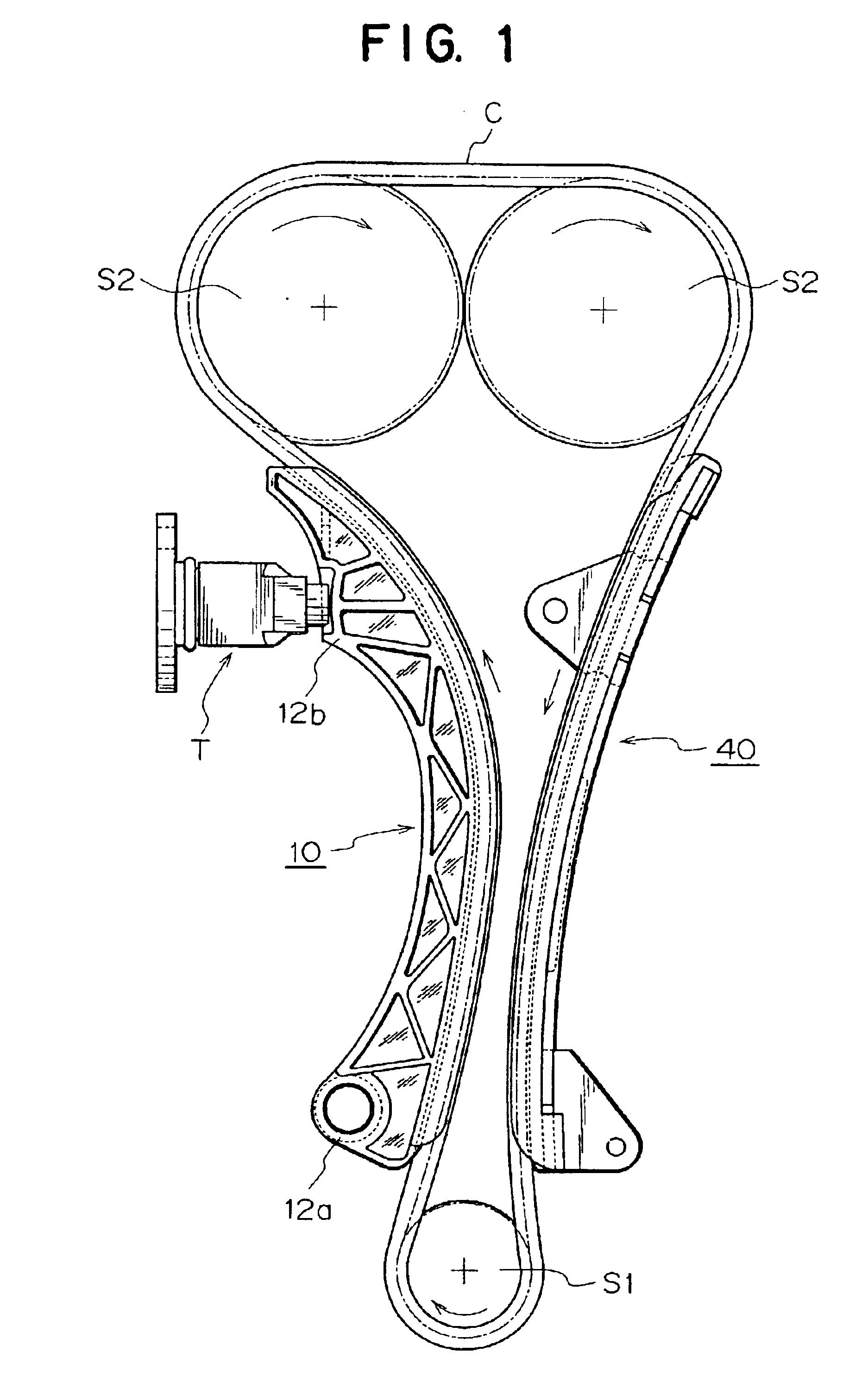
[0043]FIGS. 1-5 relate to a sandwich-molded guide 10 for a transmission device in accordance with the invention.

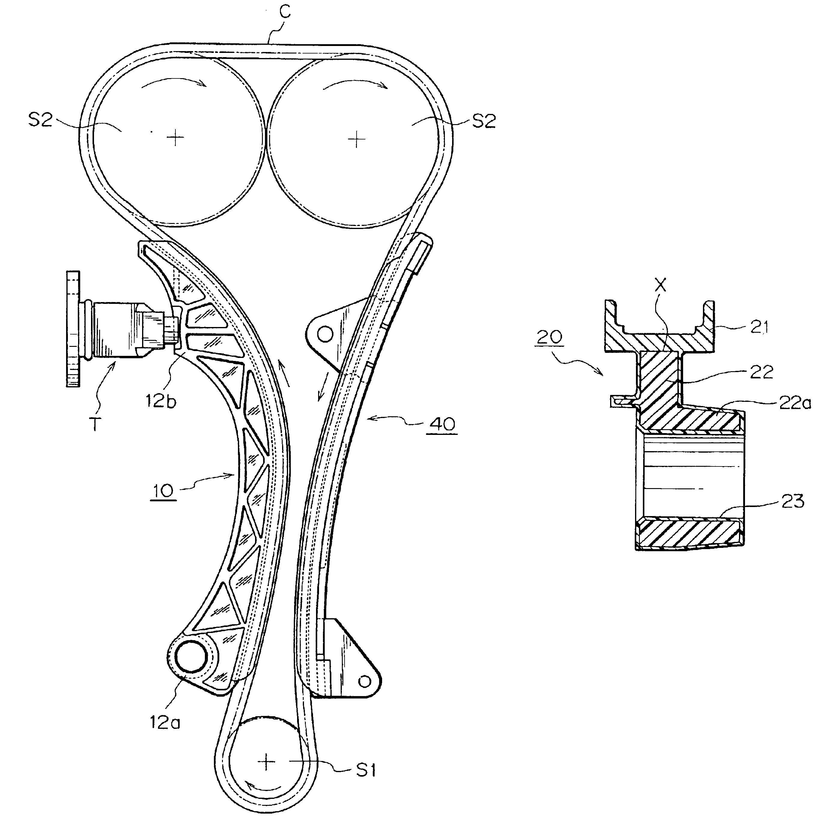
[0044]As shown in FIG. 1, a sandwich-molded guide 10 for a transmission device, in accordance with this embodiment, is used inside a motor vehicle engine in which power is transmitted by an endless chain C, which travels in a circulating path around a driving sprocket S1 and a driven sprocket S2. More specifically, the sandwich-molded guide 10 is used as a movable guide, over which the chain C slides, and which controls tension in the chain.

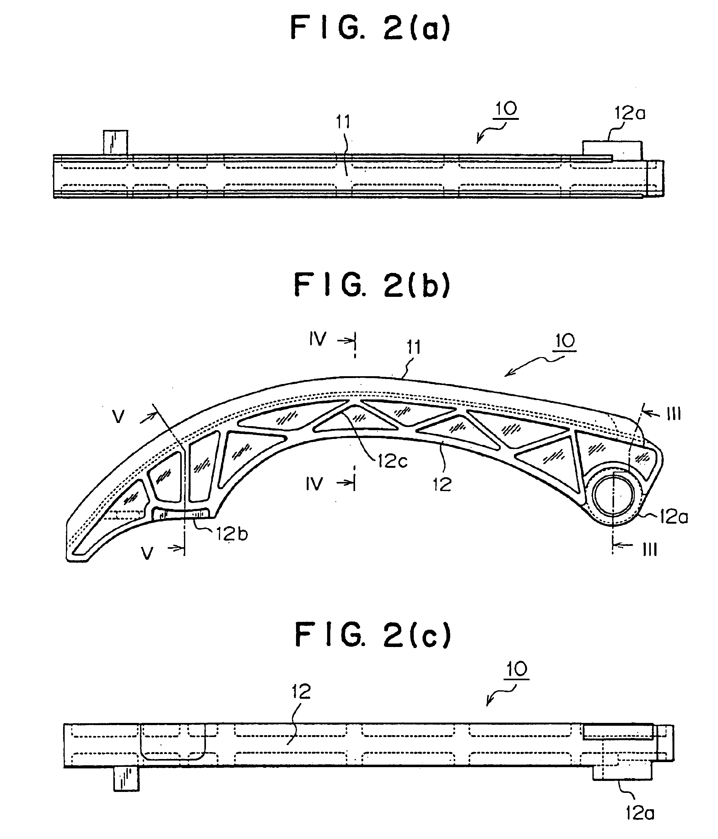
[0045]As shown in FIGS. 2(a) and 2(b), the sandwich-molded guide 10 comprises a slide rail 11 having a substantially arc-shaped contact surface on which the chain C (FIG. 1) slides. The guide comprises a rail supporting member 12, provided on and projecting vertically from the back of slide rail 11. The rail supporting member 12 extends longitudinally along the length of the slide rail 11, and projects from the rear of the slide rail in...

second embodiment

[0050]FIGS. 6-9 relate to a sandwich-molded guide 20 for a transmission device in accordance with the invention.

[0051]As in the case of the sandwich-molded guide 10 of the first embodiment, the sandwich-molded guide 20 comprises a slide rail 21 having a substantially arc-shaped sliding contact surface on which a circulating chain C slides. The guide also comprises a rail supporting member 22, provided on and projecting vertically from the back of slide rail 21. The rail supporting member 22 extends longitudinally along the length of the slide rail 11, and projects from the rear of the slide rail in a direction perpendicular to the contact surface. The rail supporting member 22 includes a boss 22a having a mounting hole 23 for mounting the guide 20 on an engine block wall so that it can serve as a movable guide. The guide 20 also comprises a tensioner abutting portion 22b for engagement with a tensioner (not shown). The tensioner functions to prevent transmission failure due to exces...


PUM

PropertyMeasurementUnit
Wear resistanceaaaaaaaaaa
Strengthaaaaaaaaaa
Polymericaaaaaaaaaa

Abstract

A guide for as transmission device such as a chain or belt, is injection molded using a sandwich-molding process. The sandwhich-molded guide comprises a slide rail on which a chain or belt slides, and a rail supporting member intergrally provided along with the slide rail. The slide rail is composed of a material the principle component of which is first polymeric material having wear resistance and heat resistance, and the rail supporting member is composed of a material the principle component of which is a second polymeric material having higher strength than the material having the first polymeric material as its principle component. The slide rail and the rail supporting member are intimately joined to each other by injection molding using the sandwhich molding process.

Description

FIELD OF THE INVENTION[0001]This invention relates to a guide, composed of plastics, for a mechanical power transmission device such as a chain or a belt, in a motor vehicle engine or the like.[0002]In motor vehicle engines, mechanical power is transmitted, for example from a crankshaft to a camshaft, by a power transmission medium such as an endless chain or a belt. A chain travels in a circulating path around a driving sprocket and a driven sprocket. A belt travels in a circulating path around a driving pulley and a driven pulley. The invention relates more specifically to a guide, composed of plastics material, for a power transmission device. The guide in accordance with the invention may be used as a fixed guide, or as a movable guide, to guide and / or regulate tension in, a power transmission medium such as a chain, belt or the like, which travels over the guide, while in sliding contact with the guide.BACKGROUND OF THE INVENTION[0003]In general, in a motor vehicle engine, or o...

Claims


Application Information

Patent Timeline
IPC IPC(8): F16H7/18F16H7/00B29C45/00F16H7/08
CPCF16H7/18B29C45/00F16H2007/0872
Inventor INOUE, KOZOONO, OSAMUMATSUMURA, SHUUJIYAMAWAKI, KOJI
Owner TSUBAKIMOTO CHAIN CO
Learn More