
Variable pulse width and pulse separation clock generator

a clock generator and variable pulse technology, applied in the field of clock signals, can solve the problem of limited maximum allowable frequency

Inactive Publication Date: 2005-05-10
IBM CORP
View PDF21 Cites 11 Cited by
  • Summary
  • Abstract
  • Description
  • Claims
  • Application Information

AI Technical Summary

Benefits of technology

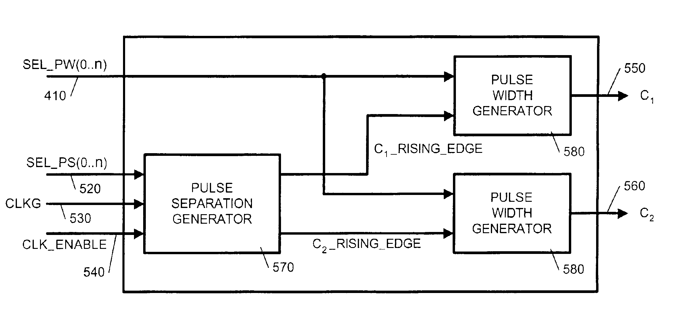
[0018]The present invention provides a clock pulse generator for generating at least two clocked pulse signals from a global clock signal. The clock pulse generator includes at least one input for receiving a clock signal having a rising and a falling edge and a mechanism for selectably delaying a rising edge of a pulse signal synchronized to the falling edge o

Problems solved by technology

In this case, the maximum allowable frequency is limited to the setup and hold time requirements of the individual physical components that make up the dynamic digital logic circuit.

Method used


Image

  • Variable pulse width and pulse separation clock generator
  • Variable pulse width and pulse separation clock generator
  • Variable pulse width and pulse separation clock generator

Examples


Embodiment Construction

[0028]Some conventional dynamic logic circuits may have their line out cycle through different logic states as the clock signal driving the circuits cycles through pre-charge and evaluate phases, even if values of Boolean operations being performed by the circuits do not change. That is, even if at each succeeding evaluate phase the output logic states on the output lines of those circuits remain the same, the output lines may nonetheless be transitioning to a different output state during each pre-charge phase.

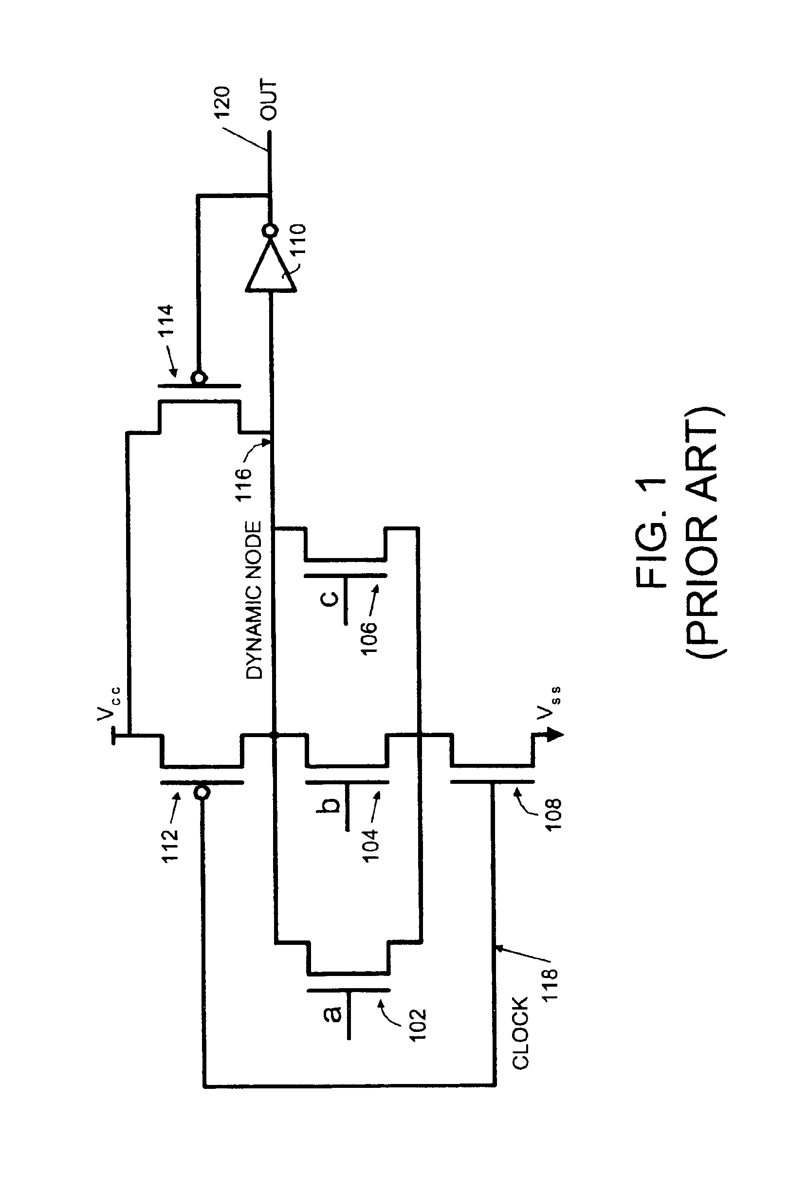
[0029]For example, suppose any one of inputs “a”, “b” and “c” of the OR-gate shown in FIG. 1 is a constant logical one (1) during two or more clock periods. Then, at each succeeding evaluate phase, there will be a logical one (1) at line out 120. However, during each pre-charge phase, the line out 120 will transition to a logical zero (0).

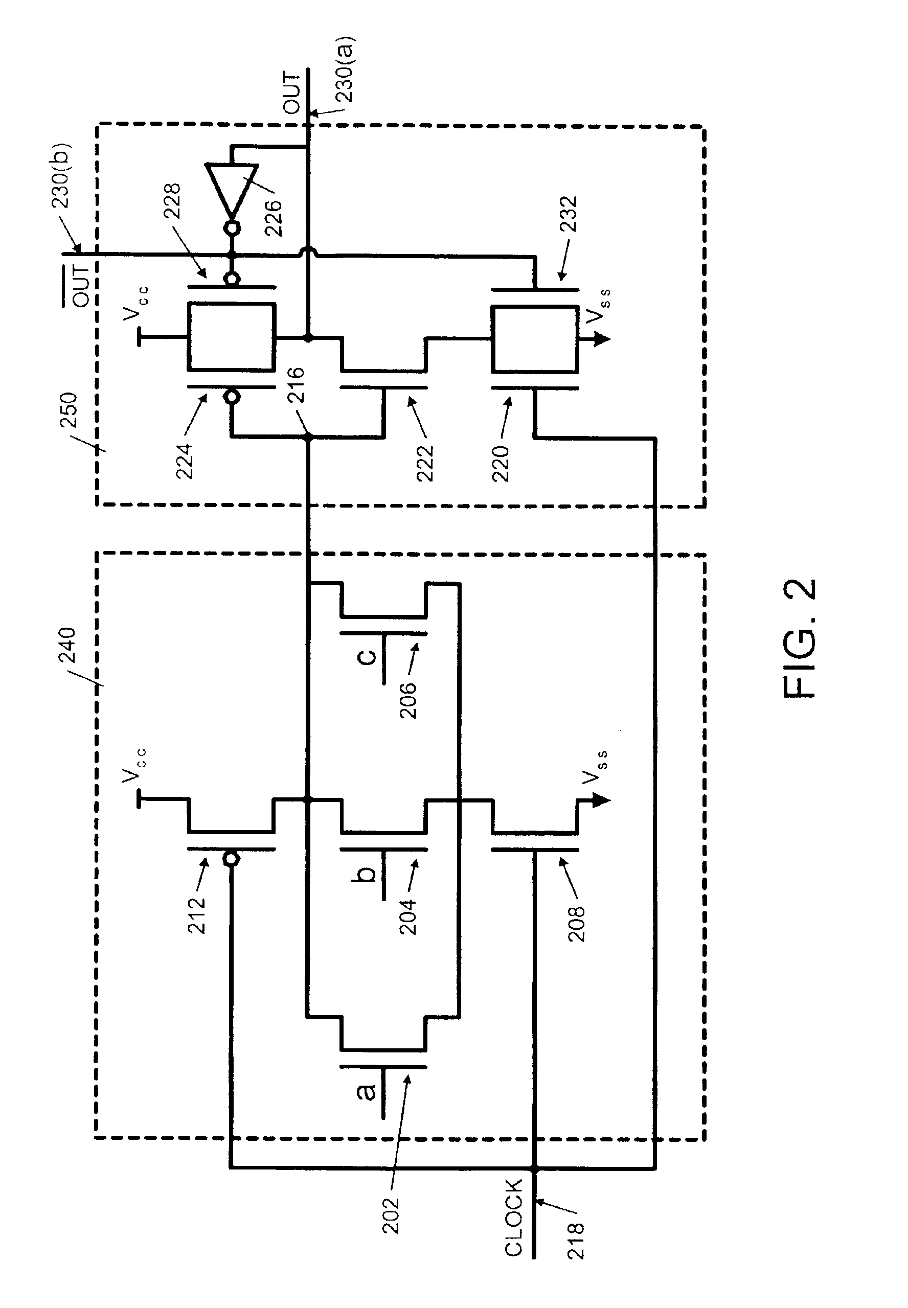
[0030]FIG. 2 depicts a three-input limited switch dynamic logic (LSDL) OR-gate circuit. The LSDL circuit is made of two portions, a dynamic...


PUM


Abstract

A clock pulse generator for generating at least two clocked pulse signals from a global clock signal is provided. The clock pulse generator includes at least one input for receiving a clock signal having a rising and a falling edge and a mechanism for selectably delaying a rising edge of a pulse signal synchronized to the falling edge of the clock signal. The clock pulse generator further includes a first selectable duration pulse synchronized to the rising edge of the clock signal and a second selectable duration pulse synchronized to the selectably delayed rising edge. The clock pulse generator also includes a glitch avoidance circuit to remove glitches in the clock signal before it is used.

Description

CROSS-REFERENCE TO RELATED APPLICATIONS[0001]The present invention is related to the following U.S. Patent Applications which are incorporated by reference.[0002]Ser. No. 10 / 116,612, filed Apr. 4, 2002, entitled, CIRCUITS AND SYSTEMS FOR LIMITED SWITCH DYNAMIC LOGIC, issued as U.S. Pat. No. 6,650,145;[0003]Ser. No. 10 / 242,214, filed Sep. 12, 2002, entitled, A LIMITED SWITCH DYNANIC LOGIC CIRCUIT, issued as U.S. Pat. No. 6,690,204; and[0004]Ser. No. 10 / 242,236, filed Sep. 12, 2002, entitled, LIMITED SWITCH DYNAMIC SELECTOR CIRCUITS.BACKGROUND OF THE INVENTION[0005]1. Technical Field[0006]The present invention is generally directed to clock signals. More specifically, the present invention is directed to a variable pulse width and pulse separation clock generator.[0007]2. Description of Related Art[0008]Dynamic logic is extensively being used in designing high-speed complementary metal oxide semi-conductor (CMOS) circuits. Dynamic logic circuits are clocked circuits. Specifically, a d...

Claims


Application Information

Patent Timeline
IPC IPC(8): G06F1/08H03K5/159H03K7/08
CPCG06F1/08H03K7/08H03K5/159
Inventor NGO, HUNG CAIBELLUOMINI, WENDY ANNMONTOYE, ROBERT KEVIN
Owner IBM CORP
Learn More