[0014]According to the invention, a hoisted load is moved by the turning movement of the upper revolving superstructure as well as the self-propulsion of the undercarriage so that transportation of a pipe or the like can be effectively carried out. In addition, the
pulley block is attached to the boom through the
universal joint so that even when load hoisting operation is carried out on a slope, the
wire rope wound around the pulley block can be kept in a proper winding condition without deflecting from the pulley block and therefore the load hoisting operation on a slope can be stably performed.
[0015]Preferably, the boom of the invention is of a single tubular-box-type structure. The boom of the single tubular-box-type structure has improved strength because of its simple, lightweight structure and therefore is suited for use in pipe laying operation and the like in which the pipelayer does not need to hoist a load placed far from it nor does it need to hoist a load high, but is required to have high hoisting ability.
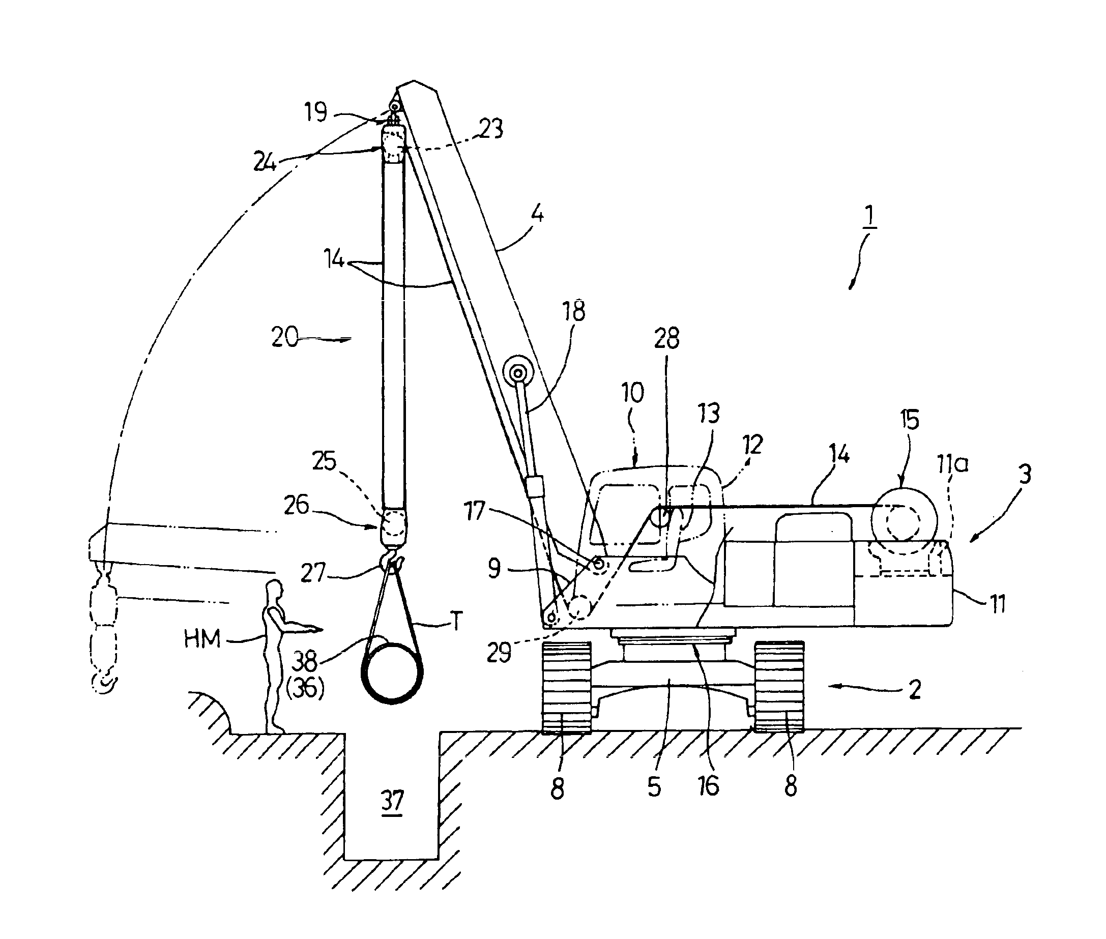
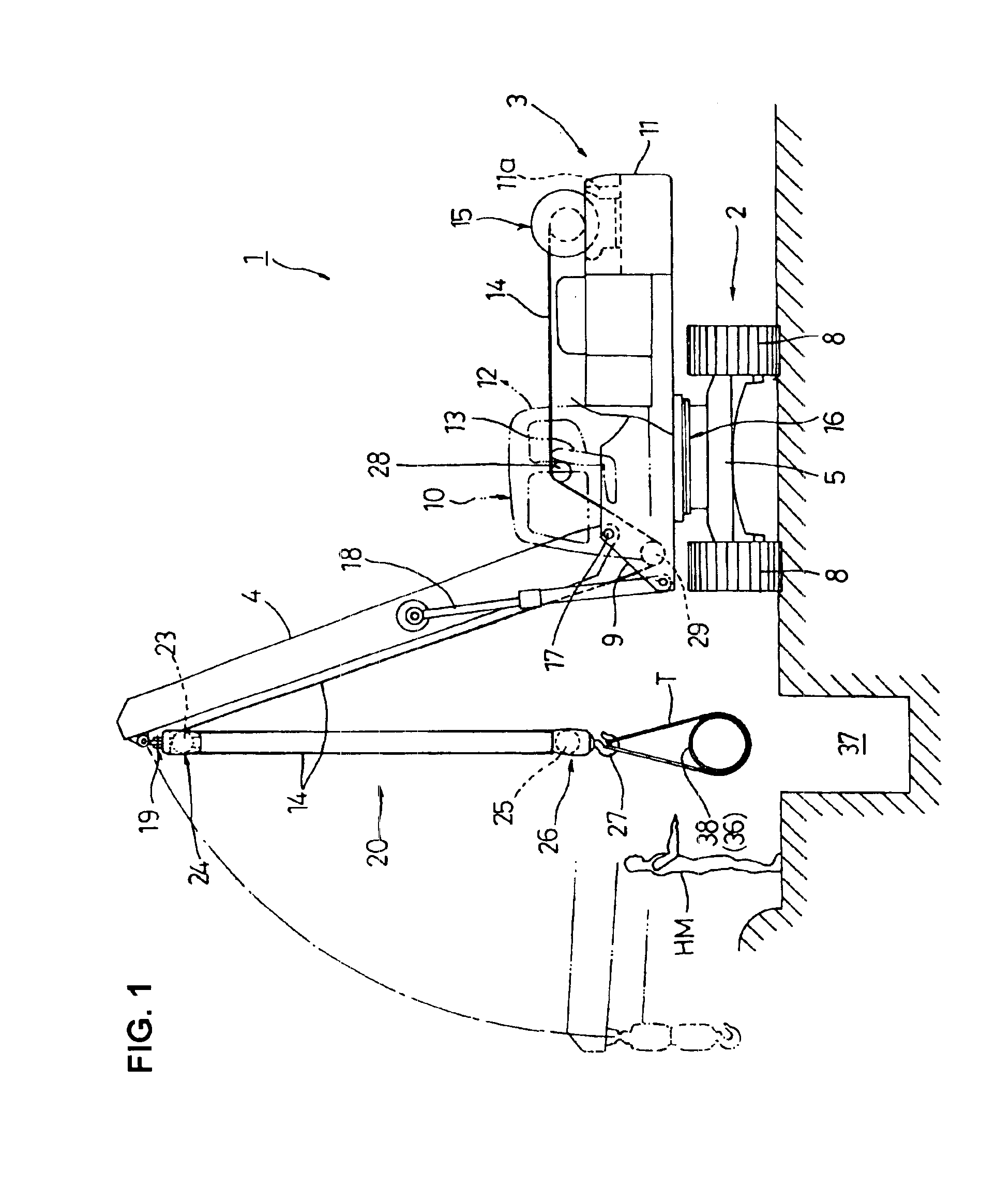
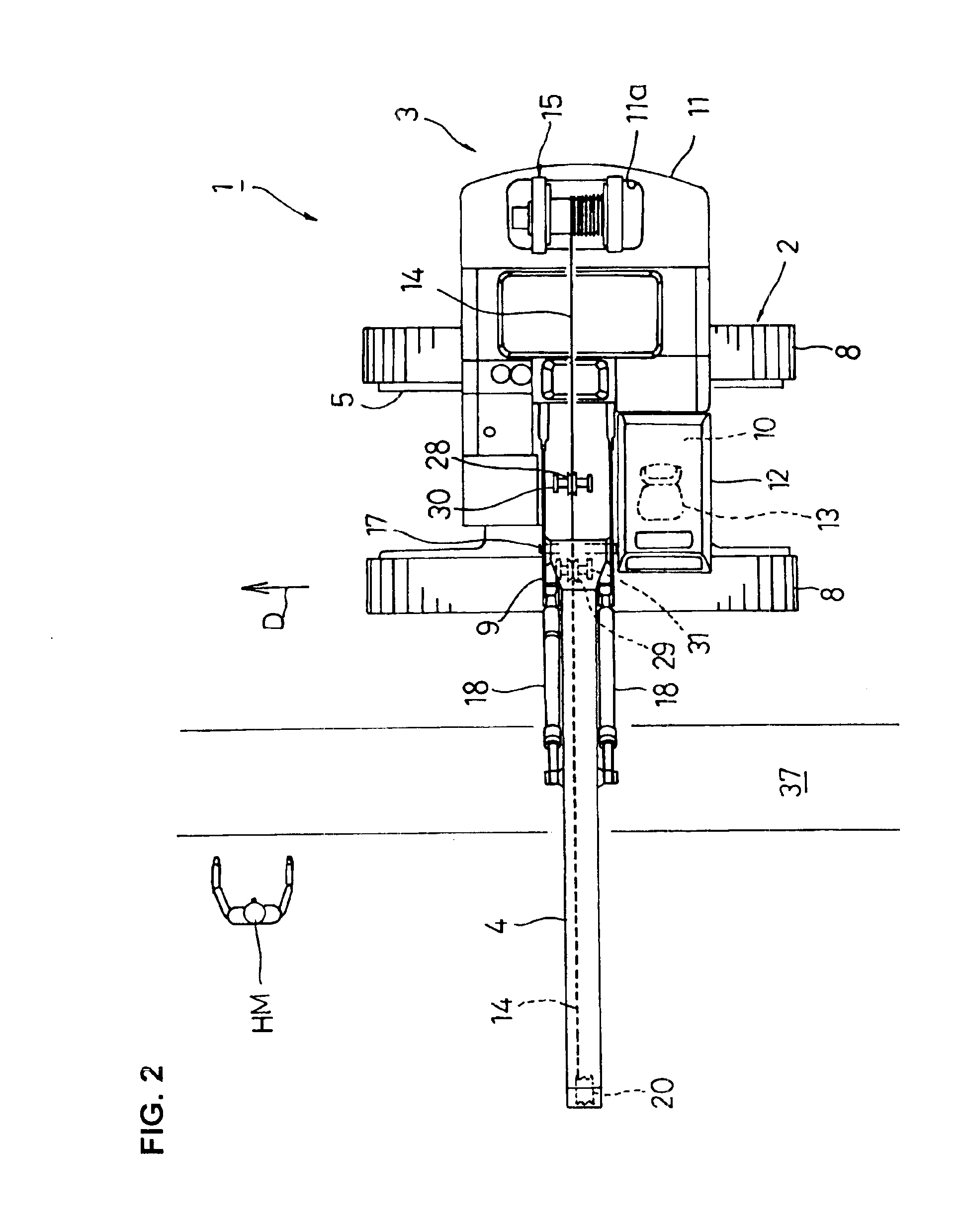
[0016]In the invention, the fulcrum of the boom relative to the upper revolving superstructure is preferably located in front of an operator's seat installed in the upper revolving superstructure. With this arrangement, the side view can be properly kept without being blocked by the boom so that the operator can visually check whether the operation is going on according to an instruction given by the hoistman.
[0017]In the invention, a derricking
system for the boom is preferably designed to raise or lower the boom through expansion and contraction of hydraulic cylinders. If a boom derricking
system designed to raise or lower the boom through operation of a derricking hoist (derricking
winch) is used for example, it becomes necessary to employ, in addition to the boom derricking
system, a means for restricting the movement of the boom when the boom is about to rise, exceeding a specified allowable angle or a special device for preventing the boom from falling down backward (e.g., boom back stop). Conversely, where the boom derricking system designed to raise or lower the boom through expansion and contraction of hydraulic cylinders is employed like the invention, unexpected situations caused by an excessive rise of the boom can be avoided by a very simple and low-cost arrangement which can be achieved without use of a special device by simply making the hydraulic cylinders come to the
stroke end when the boom rises to the maximum allowable degree. The over load
protection system (moment
limiter) typically used for cranes etc. is designed to compare a load imposed at the time of hoisting operation (i.e., actual load) with a rated total load and actuate a warning means when the actual load has reached a specified percent (e.g., 90%) of the rated total load. In the case of the
winch type boom derricking system, data on the tension of the
wire rope is required for calculation of the actual load, but such tension data is relatively difficult to detect so that there is a difficulty in construction of the over load
protection system. Conversely, in the case of the
hydraulic cylinder type boom derricking system such as used in the invention, data on the
axle load of the hydraulic cylinders can be used in place of the tension data. The
axle load data is calculated based on
pressure detection data from pressure sensors for detecting the pressures of the oil chambers on the head side and bottom side of the hydraulic cylinders respectively. The detection of the hydraulic pressures by the pressure sensors is relatively easy so that the over load
protection system can be easily constructed.
[0018]In the invention, a path for the wire
rope is preferably disposed on a side of the operator's seat located in the upper revolving superstructure. With this arrangement, the operator can watch the movement of the wire
rope so that the amount of raising and lowering the hoisted load can be obtained through
visual estimation of the amount of winding and unwinding the wire
rope with the hoist. This offers such a benefit that the height of the hoisted load can be easily adjusted.
[0019]In this case, guide sheaves for guiding the wire rope are preferably disposed on a side of the operator's seat. This makes it possible to estimate the amount of raising and lowering the hoisted load from the amount of
peripheral movement of the guide sheaves and the moving amount of the wire rope so that the height of the hoisted load can be more accurately adjusted. For further accuracy, the guide sheaves may be provided with a display unit composed of an indicator, scale marks and others.

