Two-piece stent combination for percutaneous arterialization of the coronary sinus and retrograde perfusion of the myocardium

a technology of myocardium and coronary sinus, which is applied in the field of two-piece stent combination for percutaneous arterialization of the coronary sinus and retrograde perfusion of the myocardium, can solve the problems of requiring invasive surgery, introducing devices, and not teaching how to construct such valves, and achieve the effect of convenient positioning of stents

Inactive Publication Date: 2005-05-17
MARTIN ERIC C
View PDF26 Cites 87 Cited by
  • Summary
  • Abstract
  • Description
  • Claims
  • Application Information

AI Technical Summary

Benefits of technology

[0008]The present invention contemplates a method for percutaneously providing oxygenated blood retrogradely from the left ventricle via the coronary sinus to the heart tissue without a significant left-to-right shunt. The present invention contemplates a two-piece stent combination generally having an arterializing stent and a restricting covered stent. The arterilializing stent and the restricting covered stent may optionally be connected, e.g., by a connecting wire. The arterializing stent allows aterialized blood from the left ventricle to flow directly into the coronary sinus. The arterilizing stent is fitted and expanded within a hole punctured through the coronary sinus and the wall of the left ventricle to allow fluid passageway between the left ventricle and the coronary sinus. The restricting covered stent, which is positioned so that it fits securely within the the coronary sinus, controls the amount of blood flowing from the coronary sinus into the right atrium and therefore controls the left-to-right shunt and the amount of retrograde flow to the mycardium.
[0012]The underlying arterializing stent and the underlying restricting stent are made of flexible material such as steel or nitinol that allow compression or expansion cross-sectionally. For example, each may be compressed to fit within a delivery catheter for percutaneous delivery into their desired position. And after delivery, the arterializing stent and the restricting covered stent may self expand or may be expanded using a balloon as known in the art. Generally, the arterializing stent is delivered first, followed by the delivery of the restricting covered stent. To facilitate the positioning of these stents, they are preferably marked with a radio-opaque material, such as platinum or gold. For example, the arterializing stent may include radio-opaque rings at the leading end and at the trailing end. Also, the restricting covered stent may include radio-opaque rings about the constriction, at the CS end, and / or at the RA end for fluoroscopic control.
[0014]The size of the passageway in the arterilizing stent controls the amount of blood flowing into the coronary sinus from the right atrium. The size of the constriction in the restricting covered stent controls the amount of blood flowing out of the coronary sinus into the right atrium. By diminishing the amount of left-to-right shunt, the pressure in the coronary sinus is increased and blood is increasingly directed to the myocardium retrogradely through the retrograde portion of the coronary sinus. Some amount of blood flow into the right atrium, however, is necessary to control the pressure in the coronary sinus. The diameter of the passageway at the constriction should thus be large enough to prevent the pressure inside the coronary sinus from rising above a suitable level, e.g., about 50 mm Hg or otherwise about half of systemic pressure. But at the same time, the diameter of the constriction should also be small enough to avoid excessive or deleterious left-to-right shunting. In other words, the amount of left-to-right shunting preferably does not create a significant strain on the heart. As an illustrative example only, and not as a limitation, the amount may preferably be less than approximately a one-and-a-half to one shunt ratio. These features will also be dependent on the diameter of the arterializing stent, which controls the inflow into the coronary sinus. Thus, the diameters are interdependent.

Problems solved by technology

Although Nelson requires a pressure sensitive valve that prevents pressure build-up inside the coronary sinus from rising above 60 mm Hg, Nelson does not teach how such a valve may be constructed.
Further, it is unlikely that such a device may be introduced percutaneously and will likely require invasive surgery.
The stent employed by Patel et al., however, results in a significant amount of shunting of oxygenated blood from the left ventricle to the right atrium (hereinafter “left-to-right shunt”).

Method used


Image

  • Two-piece stent combination for percutaneous arterialization of the coronary sinus and retrograde perfusion of the myocardium
  • Two-piece stent combination for percutaneous arterialization of the coronary sinus and retrograde perfusion of the myocardium
  • Two-piece stent combination for percutaneous arterialization of the coronary sinus and retrograde perfusion of the myocardium

Examples


Embodiment Construction

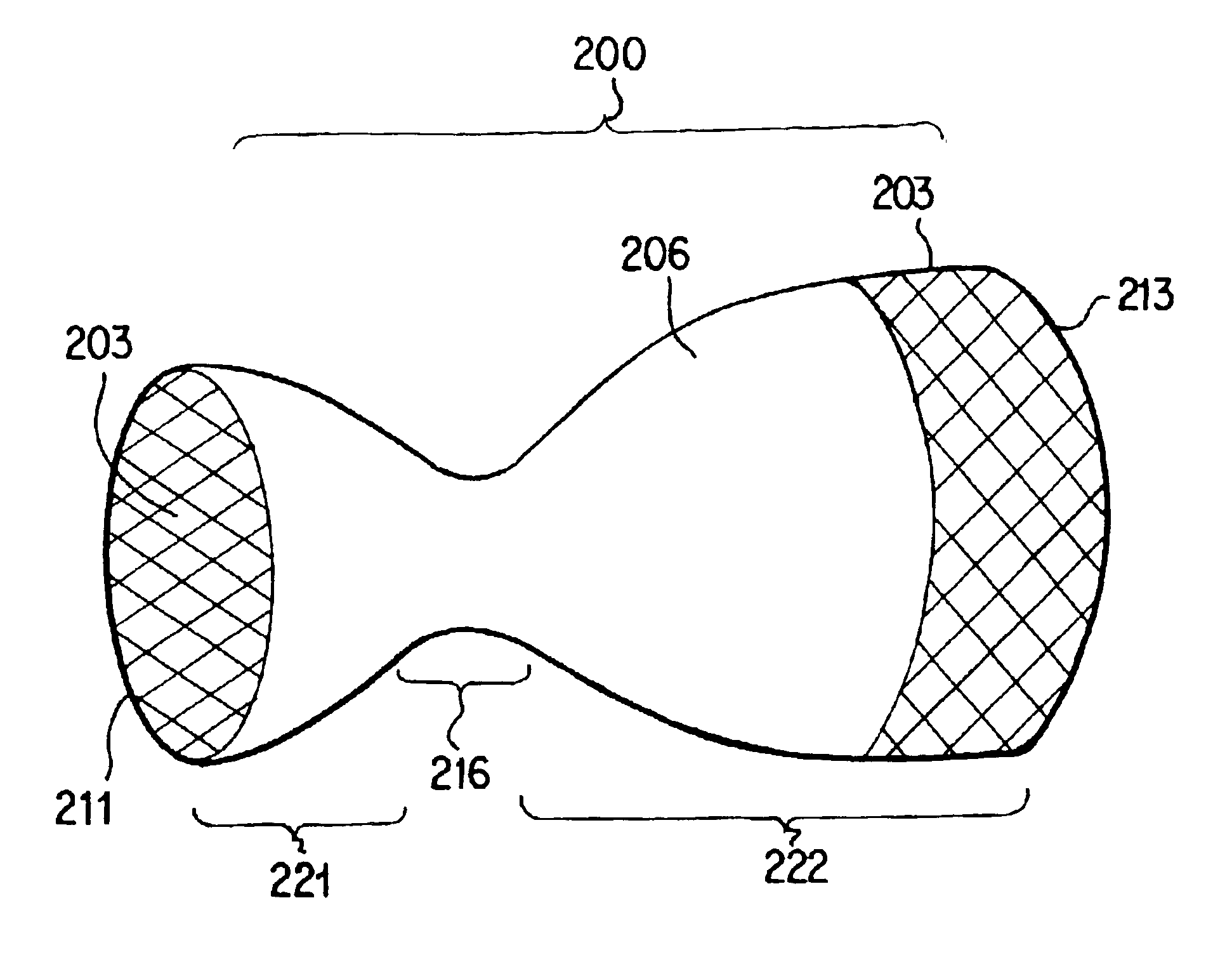
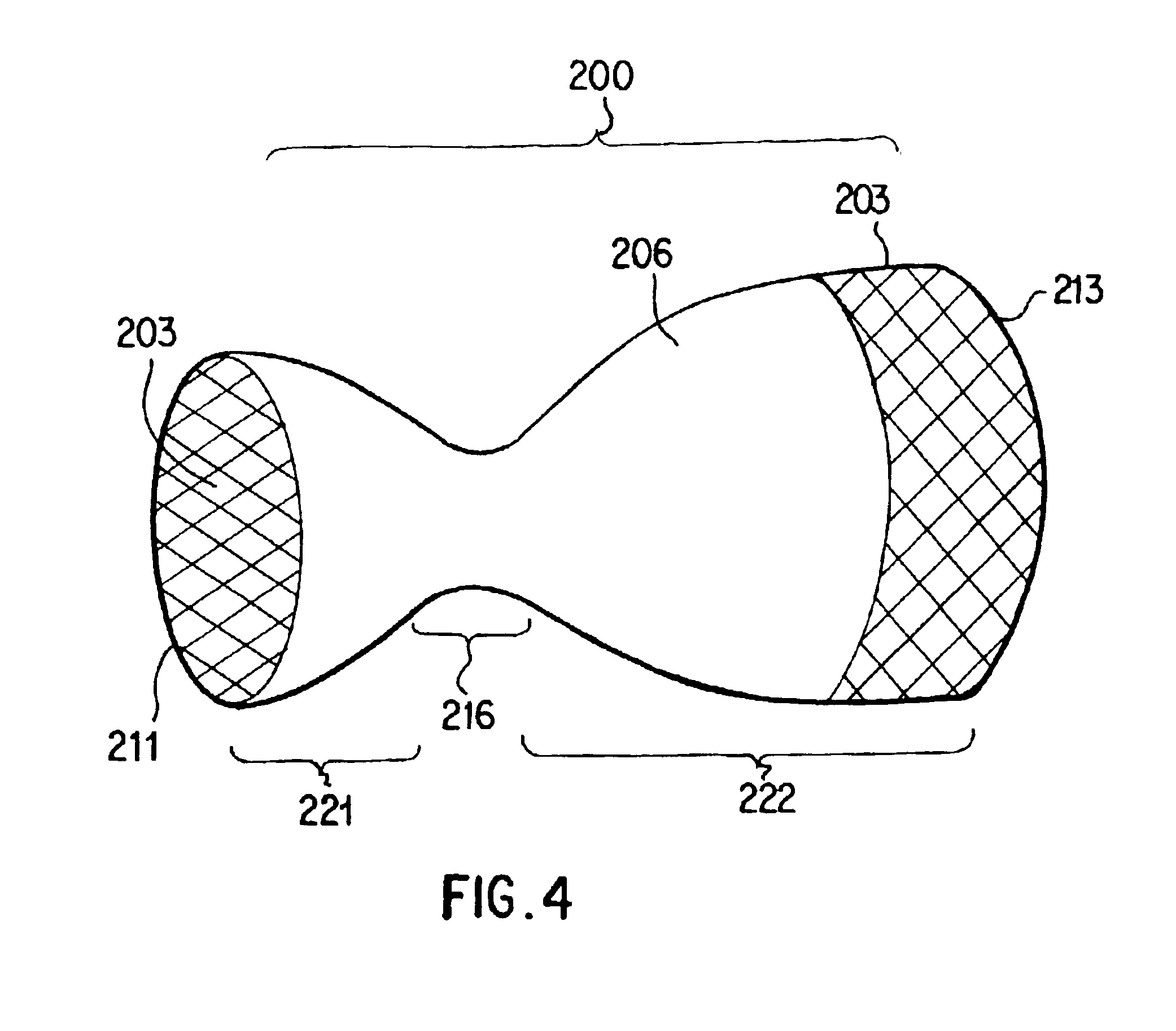
[0023]The two-piece stent combination of the present invention has an arterializing stent and a restricting covered stent. In one embodiment, the arterializing stent and the restricting covered stent are placed in their desired positions and are not connected. In another embodiment, however, the arterializing stent may be connected to the restricting covered stent, e.g., by a wire.

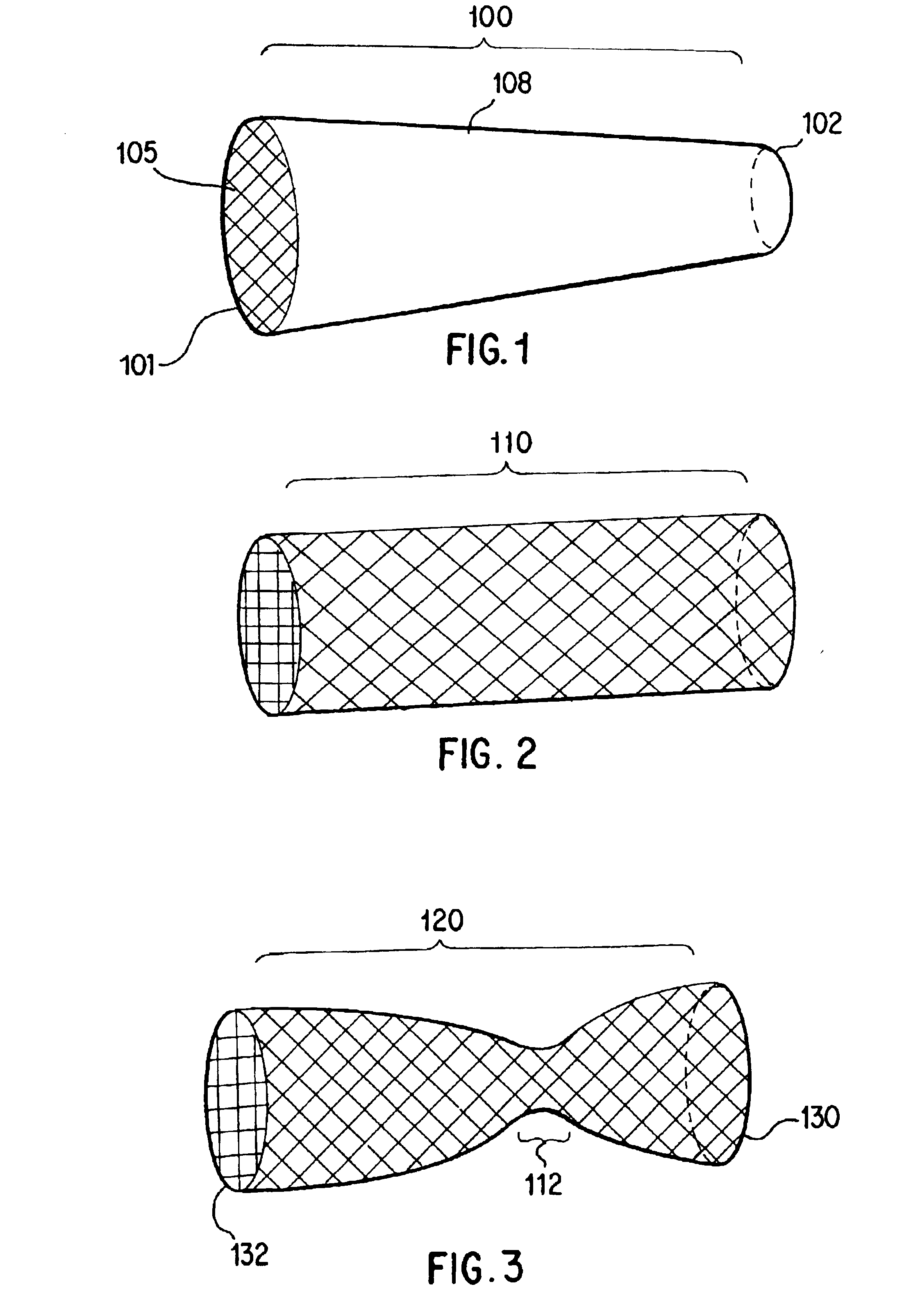
[0024]A preferred embodiment of the arterializing stent 100 according to the present invention is illustrated in FIG. 1. The arterializing stent 100 generally has an underlying arterilizing stent 105 and an optional covering 108. The arterializing stent 100 has a leading end 102, which is placed in the left ventricle, and a trailing end 101, which is placed in the coronary sinus. The arterializing stent 100 generally has a tubular shape with a passageway therethrough.

[0025]Referring to FIGS. 1-3, the shape of the arterializing stent may be one of a variety of shapes. In one embodiment, as seen in FIG. 1, i...


PUM


Abstract

The present invention contemplates a method for percutaneously providing oxygenated blood retrogradely from the left ventricle via coronary sinus to the heart tissue without a significant left-to-right shunt. The present invention contemplates a two-piece stent combination generally having an arterializing stent and a restricting covered stent.

Description

BACKGROUND[0001]I. Field of Invention[0002]The present invention concerns a two-piece stent combination for supplying oxygenated blood retrogradely from the left ventricle to the myocardium via the coronary sinus. It has an arterializing stent, which directs blood from the left ventricle to the coronary sinus, and a restricting covered stent, which controls the amount of blood flowing from the coronary sinus into the right atrium and thereby directing blood retrogradely to the myocardium.[0003]II. Description of Related Technology[0004]Retrograde perfusion of the heart through the coronary sinus has long been known for treating end-stage heart disease. Previous methods, among others, have attempted to connect the aorta to the coronary sinus during open-heart surgery using a graft of the jugular vein, the internal mammary artery, or the carotid artery. Alternatively, an occlusion balloon has been used for a short period of time.[0005]Nelson et al. (U.S. Pat. No. 5,824,071, 1998) disc...

Claims


Application Information

Patent Timeline
Patent Type & Authority Patents(United States)
IPC IPC(8): A61F2/06A61F2/00A61F2/02A61F2/07A61F2/90A61F2/95
CPCA61F2/07A61F2/2493A61F2/95A61F2002/072A61F2230/008A61F2250/0039A61F2/90A61F2230/0067A61F2250/0037
Inventor MARTIN, ERIC C.
Owner MARTIN ERIC C
Why Eureka
Try Eureka