Heat sink and semiconductor laser apparatus and semiconductor laser stack apparatus using the same

a technology of semiconductor lasers and stacking devices, which is applied in the direction of lasers, semiconductor lasers, basic electric elements, etc., can solve the problems of deteriorating the heat dissipation efficiency of devices or the like, heating sinks in accordance with the above-mentioned prior art, etc., and achieves the effect of reducing the diameter of pipes, reducing water-passing efficiency, and increasing thickness

Inactive Publication Date: 2005-05-17
HAMAMATSU PHOTONICS KK
View PDF20 Cites 10 Cited by
  • Summary
  • Abstract
  • Description
  • Claims
  • Application Information

AI Technical Summary

Benefits of technology

[0006]However, the heat sink in accordance with the above-mentioned prior art has a problem as follows. Namely, since the heat sink in accordance with the above-mentioned prior art has a pipe-like supply water path, the heat sink enhances its thickness, thereby becoming larger. Here, though the heat sink may be made thinner by reducing the diameter of pipe and so forth, the supply water path, the discharge water path, or the outer shape of heat sink will be more likely to deform due to the hydraulic pressure of the cooling water supplied to the supply water path if the heat sink is made thinner. Such a deformation may lower the water-passing efficiency of the supply water path and discharge water path, or the degree of contact between the device or the like to be cooled and the heat sink, thereby deteriorating the heat-dissipating efficiency of the device or the like. Therefore, it is an object of the present invention to provide a thin heat sink having a high heat-dissipating efficiency, and a semiconductor laser apparatus and semiconductor laser stack apparatus using the same.

Problems solved by technology

However, the heat sink in accordance with the above-mentioned prior art has a problem as follows.
Such a deformation may lower the water-passing efficiency of the supply water path and discharge water path, or the degree of contact between the device or the like to be cooled and the heat sink, thereby deteriorating the heat-dissipating efficiency of the device or the like.

Method used


Image

  • Heat sink and semiconductor laser apparatus and semiconductor laser stack apparatus using the same
  • Heat sink and semiconductor laser apparatus and semiconductor laser stack apparatus using the same
  • Heat sink and semiconductor laser apparatus and semiconductor laser stack apparatus using the same

Examples


Embodiment Construction

[0025]The semiconductor laser stack apparatus in accordance with an embodiment of the present invention will be explained with reference to drawings. The semiconductor laser apparatus and heat sink of the present invention are included in the semiconductor laser stack apparatus in accordance with this embodiment.

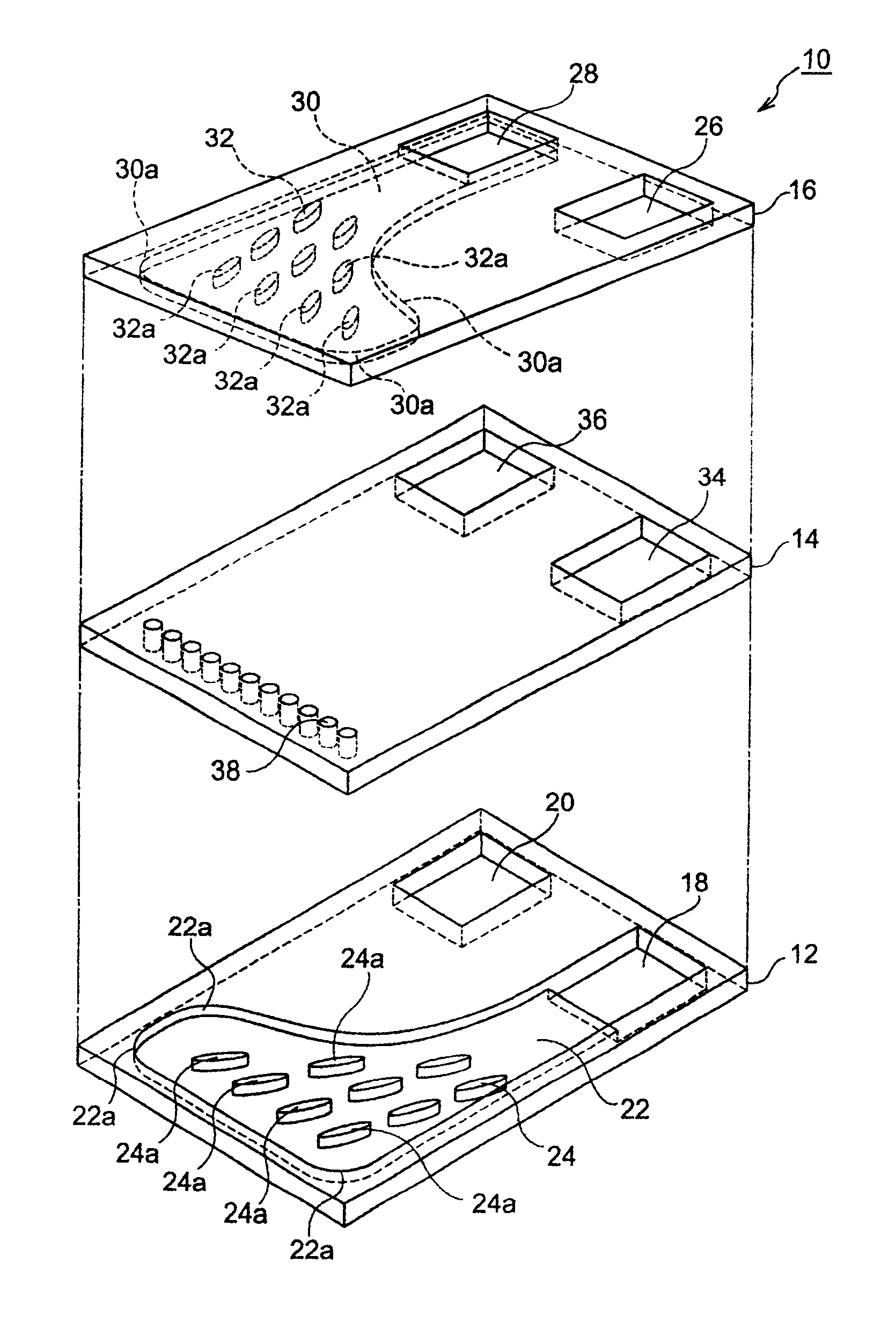
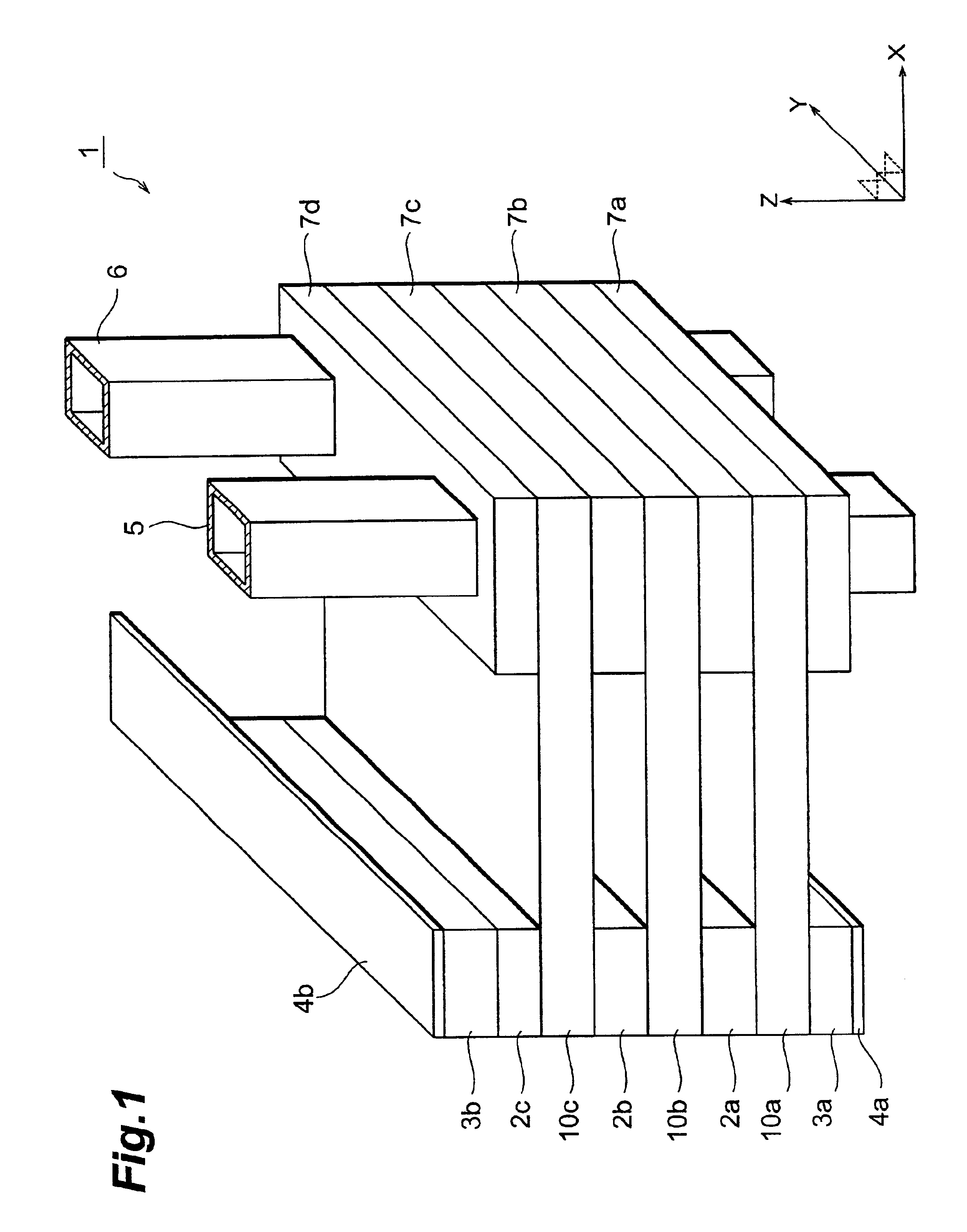
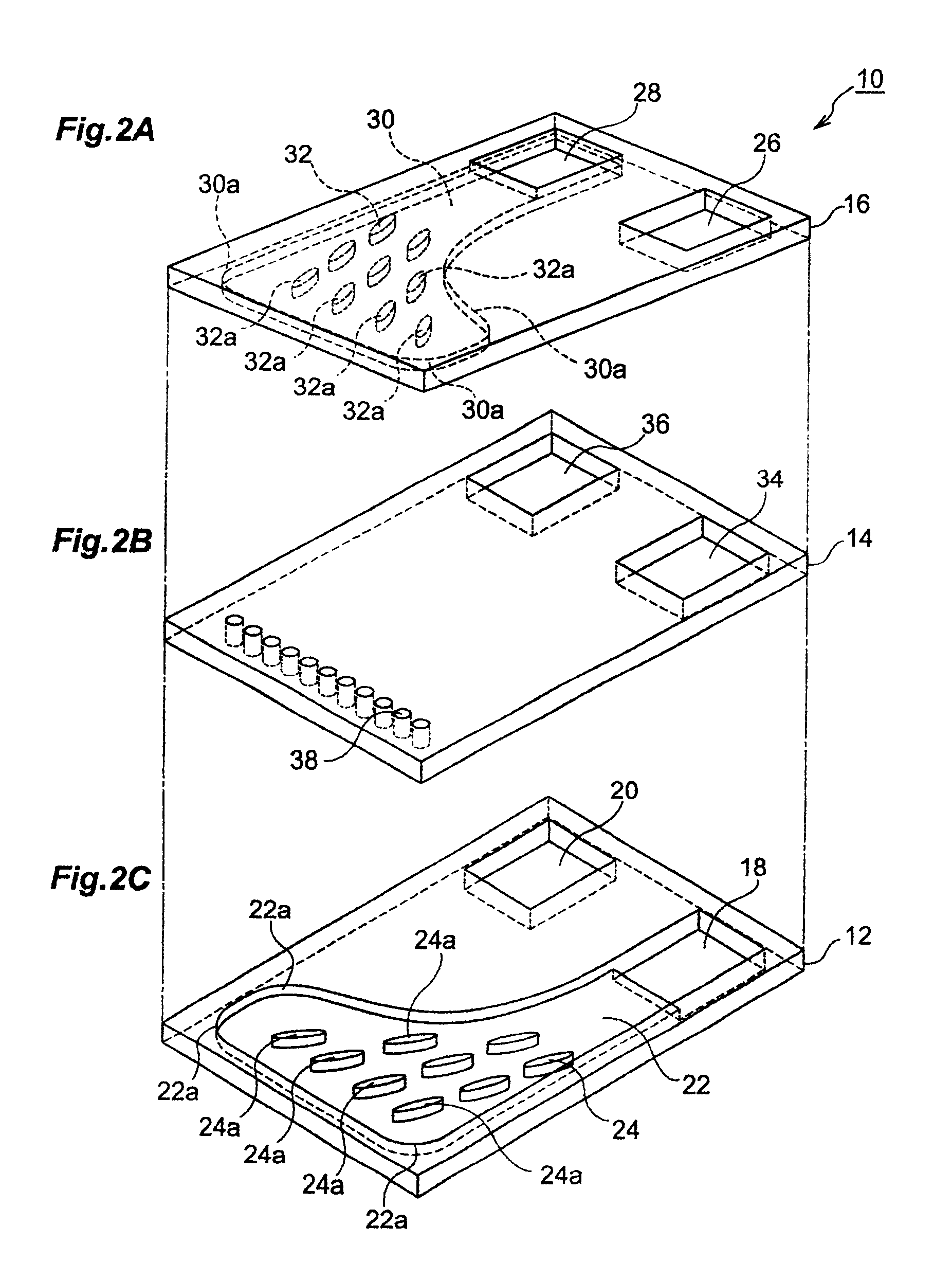
[0026]First, the configuration of the semiconductor laser stack apparatus in accordance with this embodiment will be explained. FIG. 1 is a perspective view of the semiconductor laser stack apparatus in accordance with this embodiment. As shown in FIG. 1, the semiconductor laser stack apparatus 1 in accordance with this embodiment comprises three semiconductor lasers 2a to 2c, two copper plates 3a and 3b, two lead plates 4a and 4b, a supply tube 5, a discharge tube 6, four insulating members 7a to 7d, and three heat sinks 10a to 10c. In the following, each constituent will be explained. For convenience of explanation, the positive z-axis direction and negative z-axis directi...


PUM


Abstract

A semiconductor laser stack apparatus 1 comprises three semiconductor lasers 2a to 2c, two copper plates 3a and 3b, two lead plates 4a and 4b, a supply tube 5, a discharge tube 6, four insulating members 7a to 7d, and three heat sinks 10a to 10c. Here, the heat sink 10a to 10c is formed by a lower planar member 12 formed with a supply water path groove portion 22, an intermediate planar member 14 formed with a plurality of water guiding holes 38, and an upper planar member 16 formed with a discharge water path groove portion 30 which are successively stacked one upon another, whereas their contact surfaces are joined together. The heat sink 10a to 10c is provided with pillar pieces 24 for connecting the bottom face of supply water path groove portion 22 and the lower face of intermediate planar member 14 to each other, and pillar pieces 32 for connecting the bottom face of discharge water path groove portion 30 and the upper face of intermediate planar member 14 to each other.

Description

RELATED APPLICATION[0001]The present application is a continuation-in-part application of PCT application No. PCT / JP99 / 01968 filed on Apr. 13, 1999, designating U.S.A. and now pending.BACKGROUND OF THE INVENTION[0002]1. Field of the Invention[0003]The present invention relates to a heat sink employed for dissipating heat from a heating element such as semiconductor device, and a semiconductor laser apparatus and semiconductor laser stack apparatus using the same.[0004]2. Related Background Art[0005]Known as a heat sink for dissipating heat from a heating element such as semiconductor device is one having a structure for circulating cooling water therein, such as the one disclosed in Japanese Patent Application Laid-Open No. HEI 8-139479, for example. This heat sink comprises a pipe-like supply water path for supplying pressurized cooling water, a discharge water path for discharging the cooling water, and a nozzle for injecting into the discharge water path the cooling water supplie...

Claims


Application Information

Patent Timeline
Patent Type & Authority Patents(United States)
IPC IPC(8): H01L23/473H01L23/34H05K7/20
CPCH01L23/473H01S5/02423H01S5/4031H01S5/02268H01L2924/0002H01S5/405H01L2924/00H01S5/02375
Inventor MIYAJIMA, HIROFUMIKAN, HIROFUMINAITOH, TOSHIOOHTA, HIROKAZUKANZAKI, TAKESHI
Owner HAMAMATSU PHOTONICS KK
Why Eureka
Try Eureka