
X-ray reflectometry with small-angle scattering measurement

a reflectometry and small angle technology, applied in the field of analytical instruments, can solve the problems of the difficulty inherent in performing both types of measurements using a single system

Inactive Publication Date: 2005-05-17
BRUKER TECH LTD
View PDF23 Cites 139 Cited by
  • Summary
  • Abstract
  • Description
  • Claims
  • Application Information

AI Technical Summary

Benefits of technology

[0011]The present invention provides methods and systems for performing combined XRR and SAXRS measurements on a sample. These methods and systems are advantageous, for example, in characterizing porous materials, such as low-k porous dielectrics. Although XRR and SAXRS are complementary, in terms of the information they provide, there are difficulties inherent in performing both types of measurements using a single system. In terms of irradiation of the sample, for precise measurement of SAXRS, a collimated beam is advantageous. On the other hand, XRR may advantageously use a converging beam with a large convergence angle, so that reflectivity measurements may be made over a range of several degrees simultaneously. On the detection side, SAXRS typically looks at scattering as a function of azimuth, within the surface plane of the sample, while XRR is based on measuring reflected X-rays as a function of elevation, perpendicular to the surface plane.

Problems solved by technology

Although XRR and SAXRS are complementary, in terms of the information they provide, there are difficulties inherent in performing both types of measurements using a single system.

Method used


Image

  • X-ray reflectometry with small-angle scattering measurement
  • X-ray reflectometry with small-angle scattering measurement
  • X-ray reflectometry with small-angle scattering measurement

Examples


Embodiment Construction

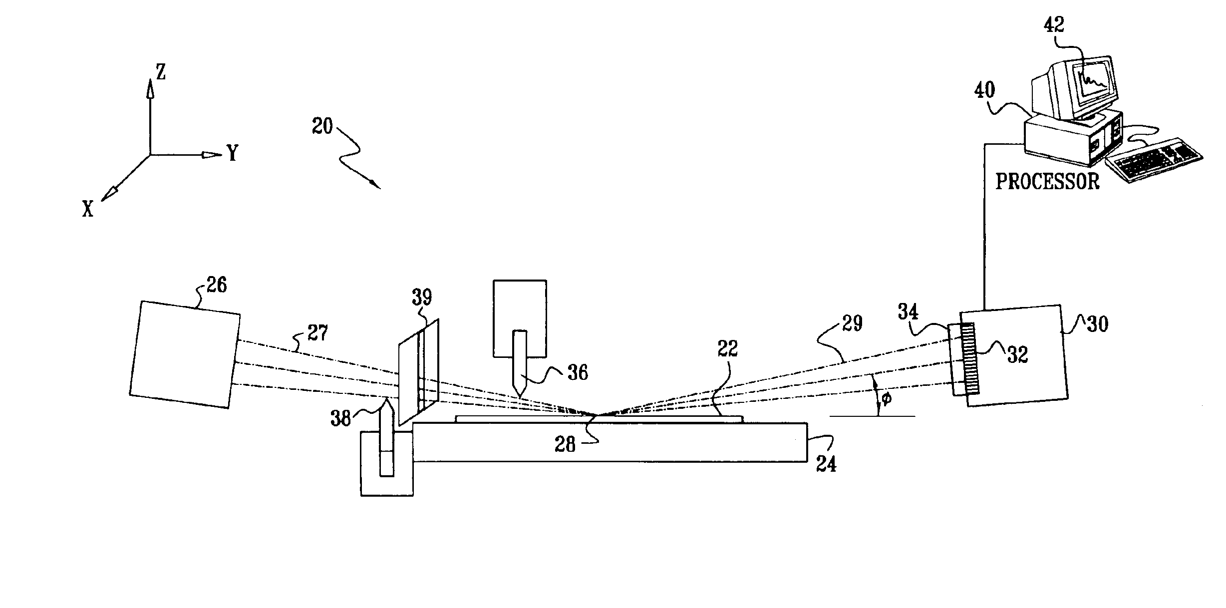
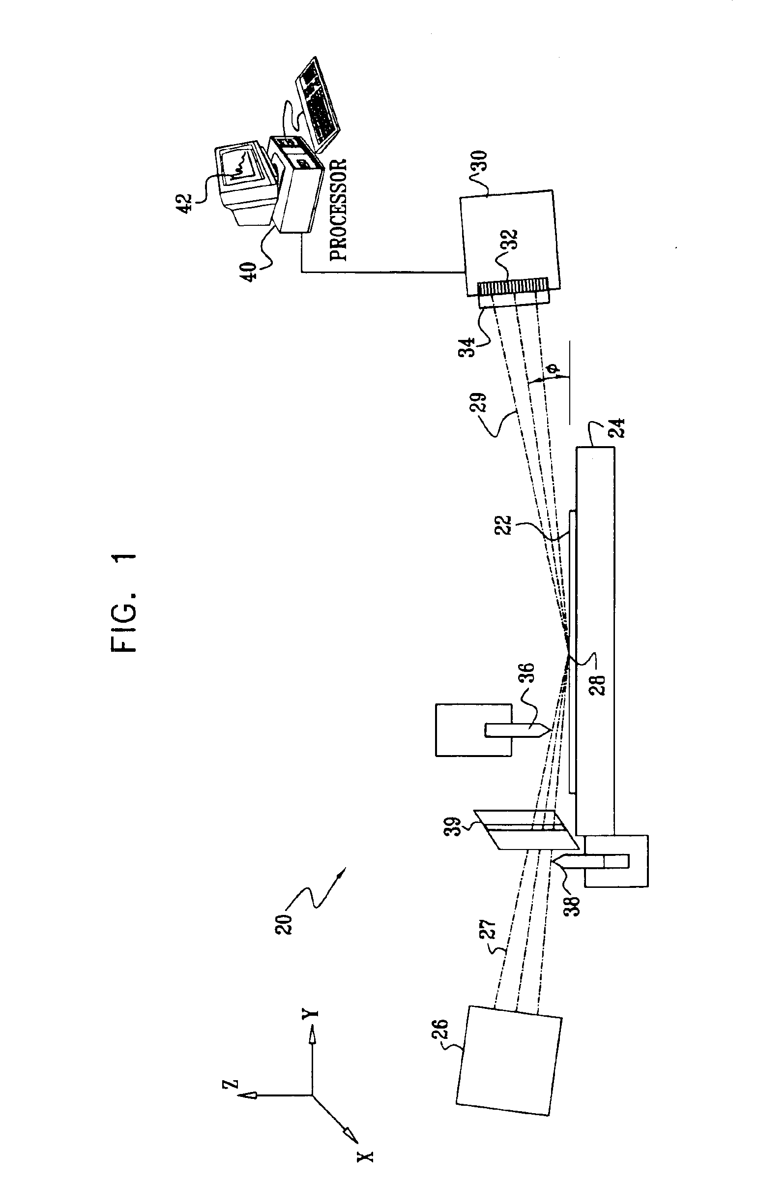
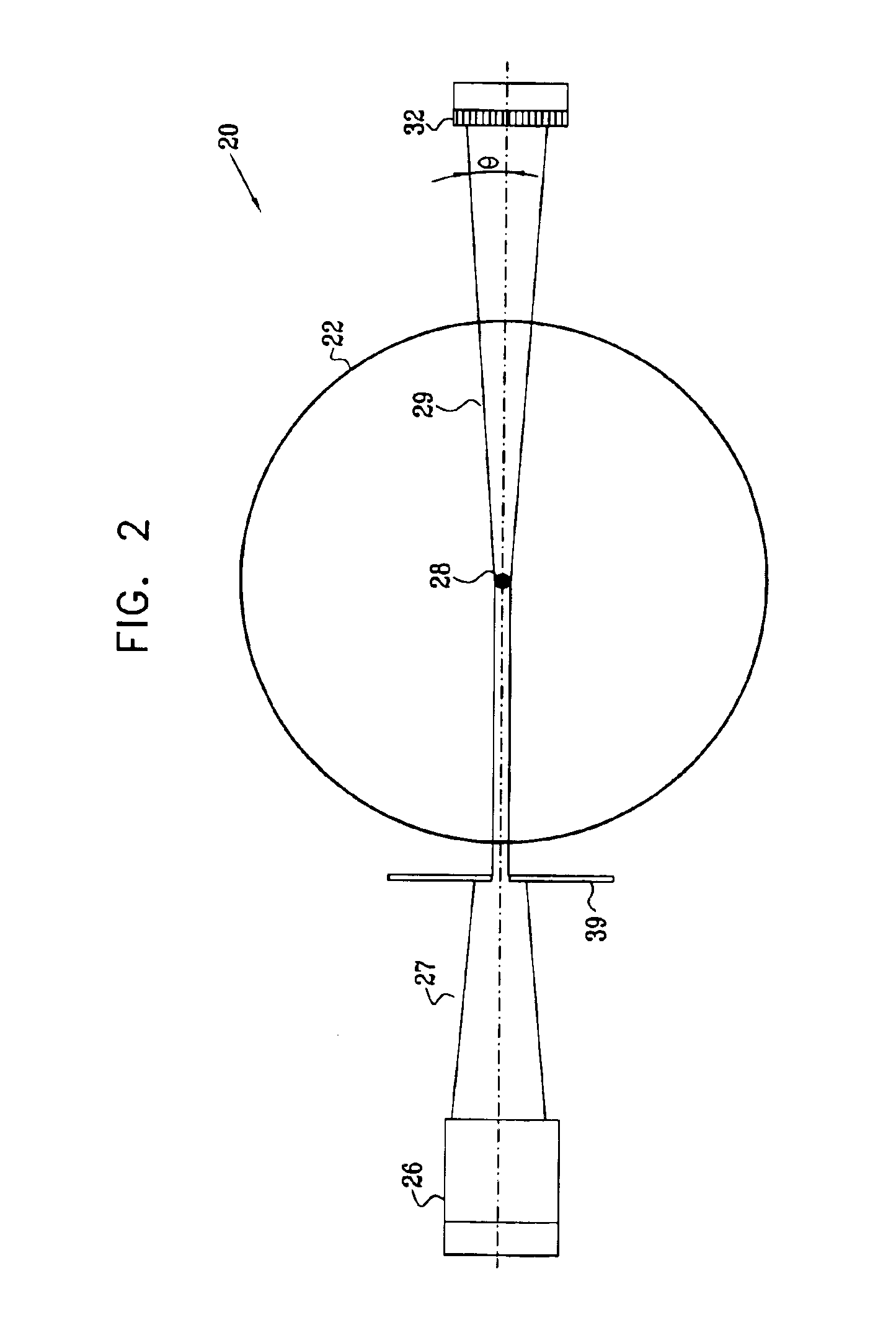
[0050]Reference is now made to FIGS. 1 and 2, which schematically illustrate a system 20 for X-ray reflectometry (XRR) and small-angle scattering (SAXRS) measurements, in accordance with an embodiment of the present invention. FIG. 1 is a side view of the system, while FIG. 2 is a top view. System 20 is similar to the XRR system described in the above-mentioned U.S. patent application Ser. No. 09 / 833,902, now U.S. Pat. No. 6,512,814 B2, with the addition of features and capabilities required for SAXRS measurement.

[0051]A sample 22, such as a semiconductor wafer, to be evaluated by system 20 is mounted on a motion stage 24, allowing accurate adjustment of its position and orientation. An X-ray source 26, typically an X-ray tube with suitable monochromatizing optics (not shown), irradiates a small area 28 on sample 22. For example, the XTF50ll X-ray tube, produced by Oxford Instruments (Scotts Valley, Calif.), may be used for this purpose. The optics focus the radiation from the X-ray...


PUM

PropertyMeasurementUnit
energyaaaaaaaaaa
angleaaaaaaaaaa
widthaaaaaaaaaa

Abstract

Apparatus for inspection of a sample includes a radiation source and an array of detector elements arranged to receive radiation from the surface due to irradiation of an area of the surface by the radiation source. The array has a first operative configuration for resolving the received radiation along a first axis perpendicular to the surface, and a second operative configuration for resolving the received radiation along a second axis parallel to the surface. A signal processor processes the signal from the detector array in the two configurations so as to determine a reflectance of the surface as a function of elevation angle relative to the surface and a scattering profile of the surface as a function of azimuthal angle in a plane of the surface.

Description

CROSS-REFERENCE TO RELATED APPLICATION[0001]This application is related to U.S. patent application Ser. No. 09 / 833,902, which was filed Apr. 12, 2001, and was published Oct. 17, 2002, as U.S. Patent Application Publication US 2002 / 0150208 A1, now U.S. Pat. No. 6,512,814 B2. This related application is assigned to the assignee of the present patent application, and its disclosure is incorporated herein by reference.FIELD OF THE INVENTION[0002]The present invention relates generally to analytical instruments, and specifically to instruments and methods for thin film analysis using X-rays.BACKGROUND OF THE INVENTION[0003]X-ray reflectometry (XRR) is a well-known technique for measuring the thickness, density and surface quality of thin film layers deposited on a substrate. Conventional X-ray reflectometers are sold by a number of companies, among them Technos (Osaka, Japan), Siemens (Munich, Germany) and Bede Scientific Instrument (Durham, UK). Such reflectometers typically operate by ...

Claims


Application Information

Patent Timeline
Patent Type & Authority Patents(United States)
IPC IPC(8): G01N23/20G01N23/201
CPCG01N23/20
Inventor YOKHIN, BORISDIKOPOLTSEV, ALEXANDERRAFAELI, TZACHIGVIRTZMAN, AMOS
Owner BRUKER TECH LTD
Learn More