Flexible milk hose for an automatic milking plant

a flexible, milking plant technology, applied in the field of milk hoses, can solve the problems of irritation of animals, marked restriction of the flexibility of the short milk hose, light shock or vibration, etc., and achieve the effects of improving the wall thickness, good stability against deformation, and moderate pri

Inactive Publication Date: 2005-05-24
MAIER JR JAKOB
View PDF24 Cites 19 Cited by
  • Summary
  • Abstract
  • Description
  • Claims
  • Application Information

AI Technical Summary

Benefits of technology

[0015]In accordance with an advantageous embodiment, the wall thickness in an elevation exceeds the wall thickness in an area in which no spaced-apart elevations exist. Due to the increased amount of material provided in the area of an elevation, the necessary mechanical stability vis-a-vis the pressure differences occurring is guaranteed, even if the effective wall thickness of the areas between two elevations on the outer edge of the curvature of the hose will be reduced when the centre piece is being bent. Hence, it is possible to produce the centre piece from a uniform material.
[0016]According to another preferred embodiment, the whole flexible milk hose is produced from a uniform material. The milk hoses can therefore be produced at a moderate price.
[0017]In accordance with a further advantageous embodiment of the present invention, the elevations and the areas between two respective neighbouring, spaced-apart elevations have substantially the same wall thickness. Due to this structural design, which is similar to that of a bellows, the milk hose is particularly flexible and it is especially also adapted to be stretched and compressed, respectively, in the longitudinal direction. By enlarging the wall thickness in this area, it is possible to achieve by means of said increased wall thickness, in spite of the bellows-like structural design, a good stability against deformations of the interior diameter caused by pressure fluctuations and to maintain simultaneously a high flexibility, especially in the longitudinal direction. In addition, this embodiment is particularly suitable for imitating the natural sucking of the calf on the teat of the brood animal on the basis of the compression and stretching taking place in the longitudinal direction of the centre piece of the flexible milk hose during the change-over from the suction phase to the relief phase. On the basis of this alternating stretching and compression of the milk hose, the pendulum motion of the milking unit produced by the pressure differences occurring during the change-over from one phase to the other will be intensified and the teats will additionally be stimulated and the muscles of the udder relaxed in the rhythm of the phase change, similar to the effect produced when a calf is sucking on the udder.
[0018]In accordance with a further preferred embodiment, the first and second end portions have each formed thereon a reinforcement element. This measure serves to achieve a higher bending stiffness especially in the connection area of the milk hose, whereby bending will substantially occur in the centre piece, as intended, when a mechanical load is applied to the milk hose. This will reduce the risk of tearing of the hose, especially at the transition from the connecting neck to the connection element.
[0019]It will be advantageous when the wall thickness of the reinforcement elements exceeds that of the residual area of the first and second end portions. It is thus possible to stiffen the end portions, even if the milk hose is produced from one uniform material.
[0020]In accordance with another preferred embodiment, the interior diameter of the centre piece does not vary in this area. In the case of this embodiment, the flow of the stream of milk will not be impaired by interaction with the inner surface, e.g. by the formation of vortices on indentations on said surface. Furthermore, the fluid connection element can be cleaned easily.

Problems solved by technology

The change over from the suction phase to the relief phase takes place approx. 60 times per minute and leads to light shocks or vibrations due to the pressure fluctuations occurring during the change from one phase to the other and due to the change in the conditions under which the teat cup adheres to the teat.
This has the consequence that the originally desired flexibility of the short milk hoses is markedly restricted.
This leads to tensions at the udder and therefore to an irritation of the animal and it may cause a premature interruption of the flow of milk in the case of the udder quarters which have not yet been emptied.
In addition, the constant twisting and bending forces acting on the short milk hoses entail a high degree of wear of the short milk hoses and a resultant fracture of the material, in particular at the transition points to the connection necks leading to the teat cups and the directional valve, respectively.

Method used


Image

  • Flexible milk hose for an automatic milking plant
  • Flexible milk hose for an automatic milking plant
  • Flexible milk hose for an automatic milking plant

Examples


Embodiment Construction

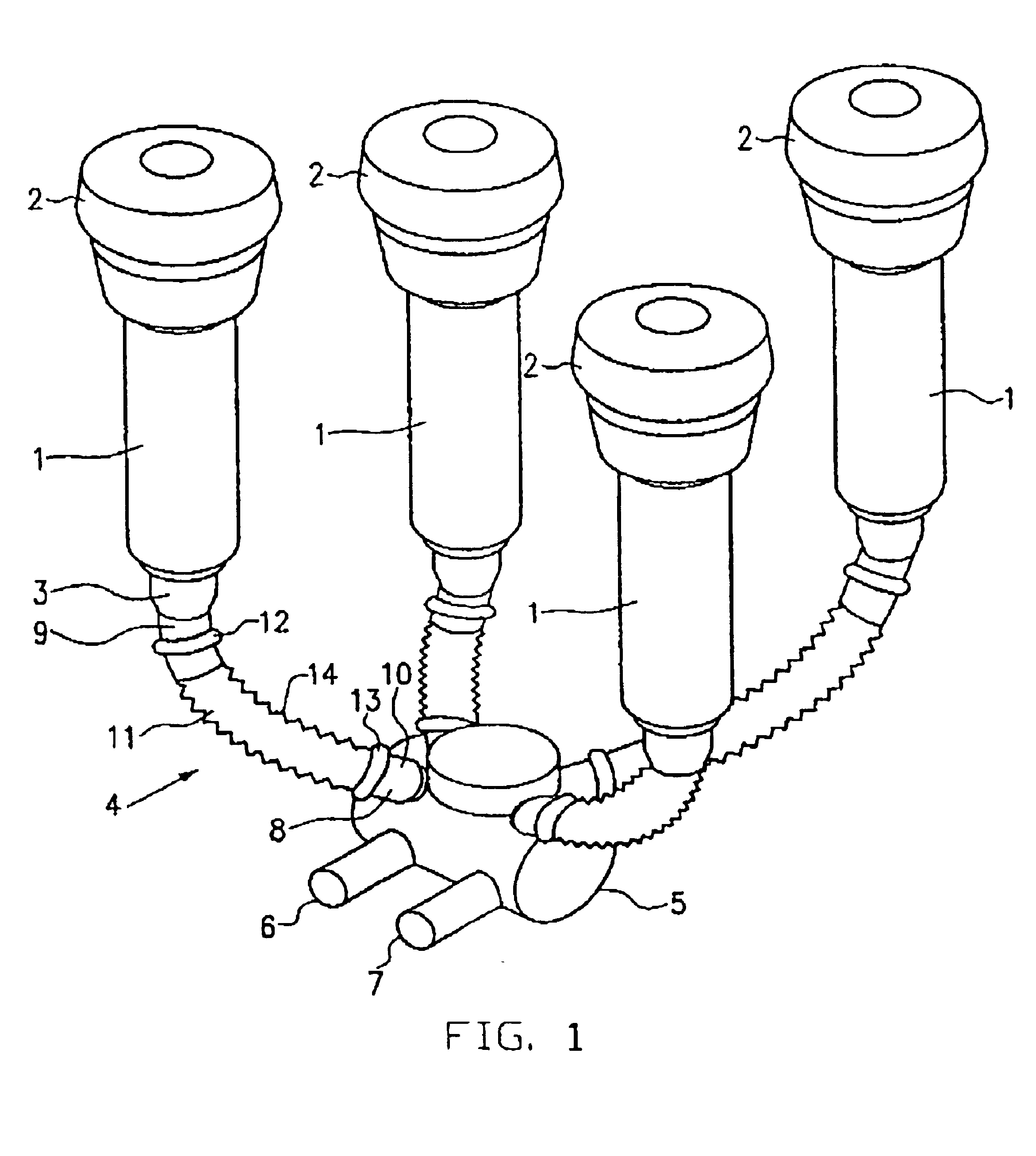
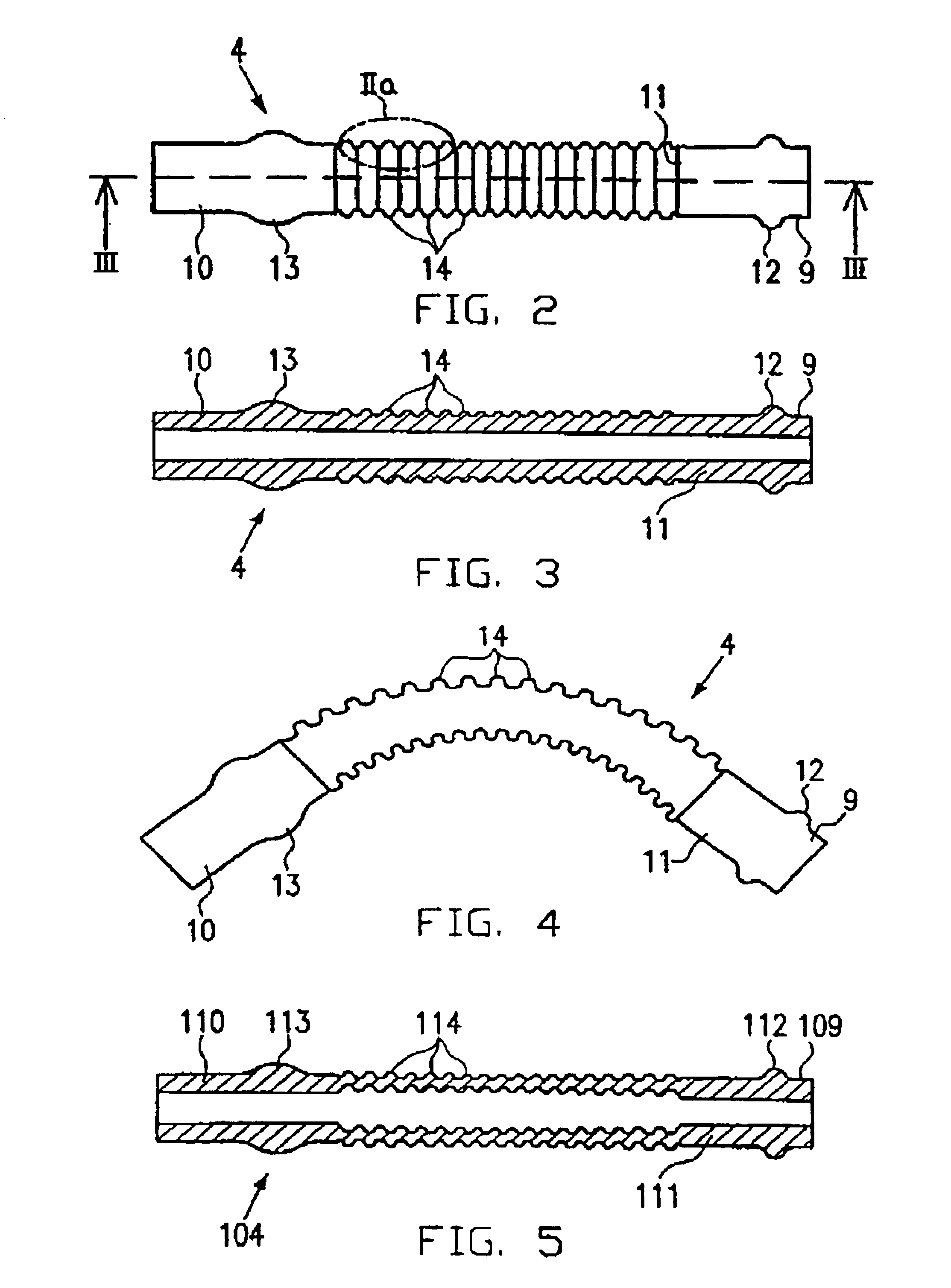
[0036]A first embodiment is now explained making reference to FIGS. 1, 2 and 3.

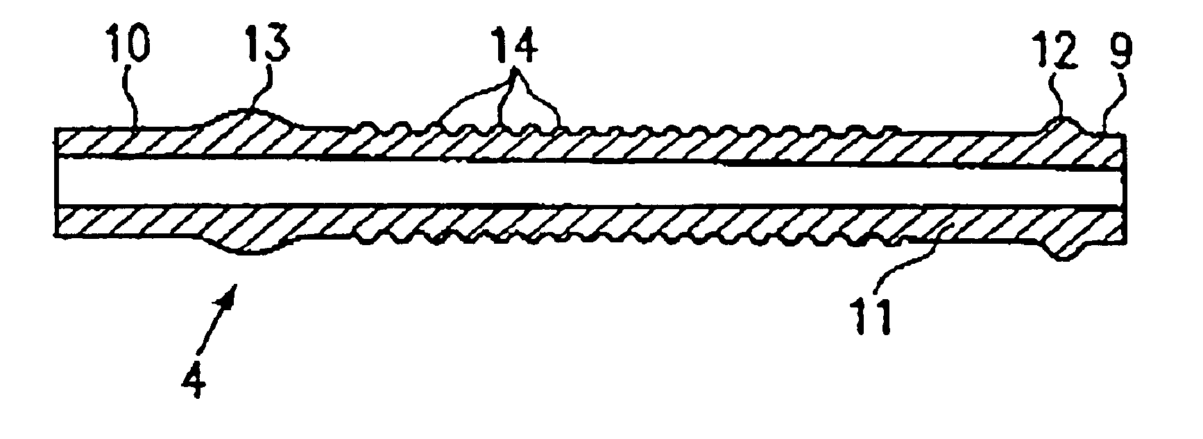
[0037]FIG. 1 shows the fundamental structural design of a milking unit in which short milk hoses are used in accordance with one embodiment of the present invention. Reference numeral 1 stands for the four teat cups at the upper edge of which the bulge of the teat rubber 2 is formed. The outlet neck 3 is arranged at the other end of the teat cup 1. The teat rubber 2 extends in the interior of the teat cup 1 down to the outlet neck 3. An inlet neck for the connection conduit by means of which fresh air is blown into the area between the teat cup 1 and the teat rubber 2 so as to change over from the suction phase to the relief phase is not shown in FIG. 1 for the sake of clarity. The outlet necks 3, which are formed on or attached to the teat rubbers, have short milk hoses 4 connected thereto. Instead of being separate parts, the teat rubber and the short milk hoses can also be implemented as an integral co...


PUM


Abstract

An automatic milking plant is provided with a short milk hose, which, due to spaced-apart elevations in its center piece, has sufficient mechanical stability vis-a-vis pressure differences as well as a high flexibility. The use of the short milk hose according to the present invention leads to a reduction of the mechanical strain on the udder and thus also reduces irritations of the animal to be milked.

Description

FIELD OF THE INVENTION[0001]The present invention relates to a milk hose for establishing a fluid connection, especially for connecting a teat cup to a multiway valve in an automatic milking plant.BACKGROUND OF THE INVENTION[0002]The increasing globalization of the agrarian markets necessitates an increasing degree of rationalization also in agricultural enterprises. Milk producing enterprises use therefore almost exclusively automatic milking plants. Hence, these plants have, on the one hand, the function of markedly increasing the milking capacity, i.e. they should be able to milk more animals per unit time, so as to increase the productivity of the agricultural enterprise, and, on the other hand, the physical and also the psychical strain to which the animals are subjected by the mechanical milking process should be reduced to a minimum by these plants.[0003]An ideal milking plant should therefore be capable of processing during the milking operation a big flow of milk adapted to...

Claims


Application Information

Patent Timeline
Patent Type & Authority Patents(United States)
IPC IPC(8): A01J5/04A01J5/00
CPCA01J5/044
Inventor MAIER, JR., JAKOB
Owner MAIER JR JAKOB
Why Eureka
Try Eureka