Method of determining the crankshaft position of an internal combustion engine

a crankshaft position and internal combustion engine technology, applied in the direction of machines/engines, electrical control, instruments, etc., can solve the problems of limited maximum number of reference marks, no significant increase in the number of reference marks situated on the sensor wheel, and the method described, so as to achieve further improvement of the result of extrapolation and the effect of extrapolation

Inactive Publication Date: 2005-05-24
ROBERT BOSCH GMBH
View PDF7 Cites 6 Cited by
  • Summary
  • Abstract
  • Description
  • Claims
  • Application Information

AI Technical Summary

Benefits of technology

[0010]In the method according to the present invention, the extrapolation may basically be performed in different ways. In a simplest variant, only those crankshaft positions are considered which have been initially determined from the camshaft positions detected by the absolute angle sensor. The result of the extrapolation may be improved by additionally c

Problems solved by technology

For lack of space, the sensor wheel attached to the camshaft is relatively small so that the number of reference marks situated on the sensor wheel may not be significantly increased.
Moreover, the maximum number of the reference marks is limited by the resolution capability of the camshaft sensor.
Due to this fact, the method described in German Published Patent Application No. 43 13 331 for determining the crankshaft position of an engine in the event of failure of the crankshaft sensor has been found problematic.
In particular in the lo

Method used


Image

  • Method of determining the crankshaft position of an internal combustion engine
  • Method of determining the crankshaft position of an internal combustion engine

Examples


Embodiment Construction

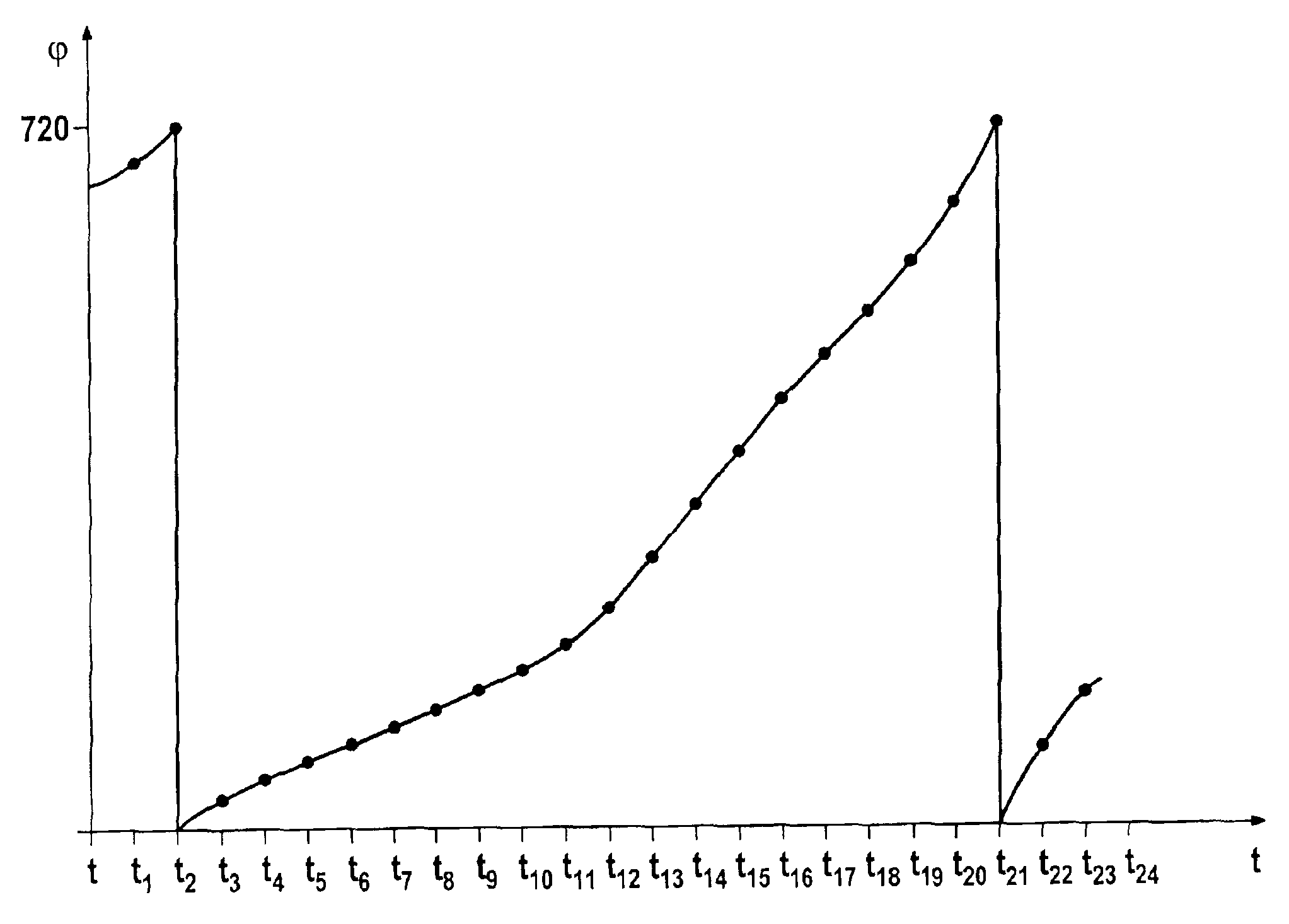
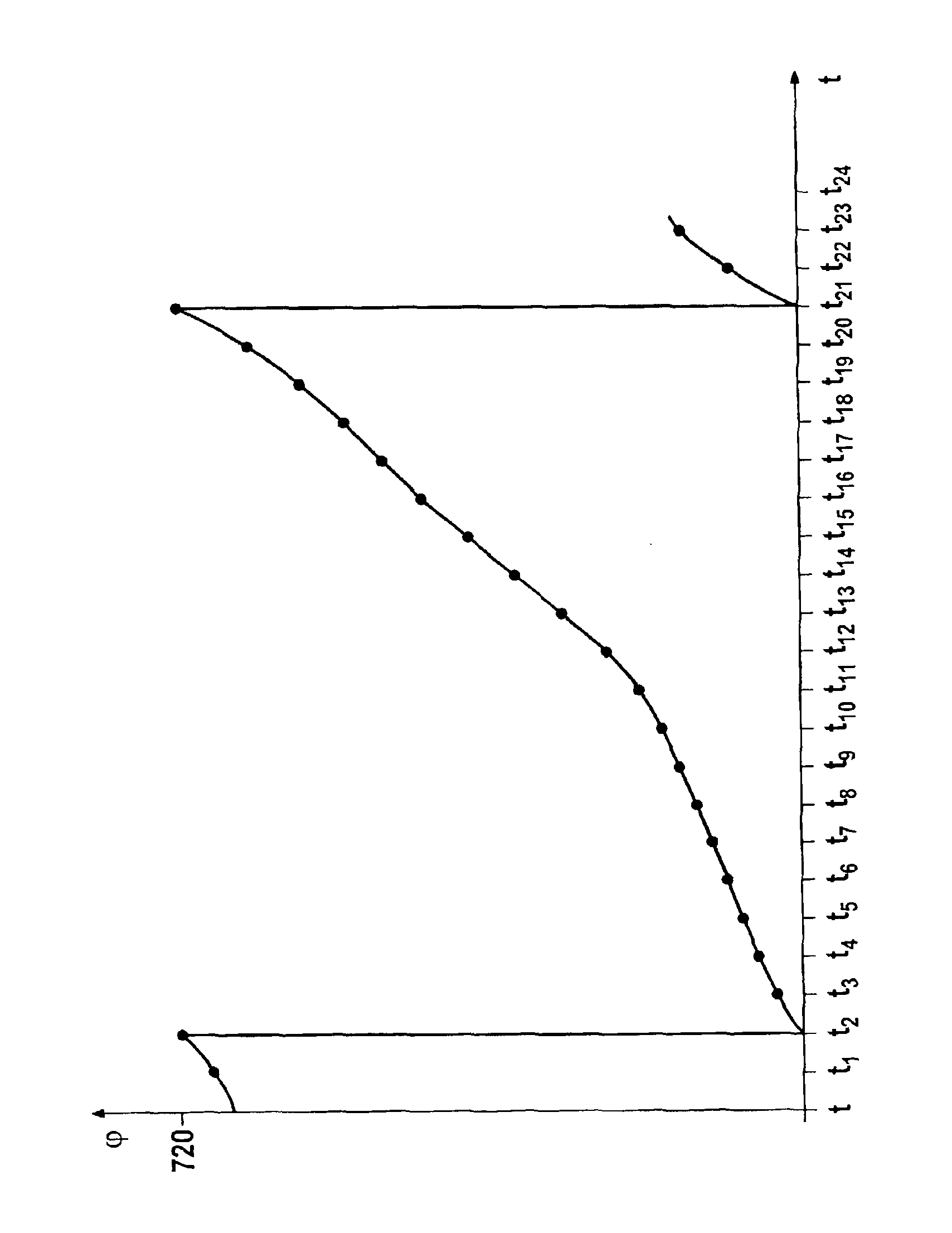
[0012]A sensor wheel having (60-2) or (36-2) angle marks in the form of teeth is frequently used in practice for the rotational speed detection at the crankshaft. This sensor wheel is permanently attached to the crankshaft, thus rotating with it. The angle marks are scanned by a crankshaft sensor which, for example, operates inductively, magnetoresistively, or utilizes the Hall effect. Each angle mark of the sensor wheel thus represents a defined crankshaft position. The output signal of the crankshaft sensor is transformed into a square-wave signal, each rectangular pulse reflecting the appearance of an angle mark and thus a defined crankshaft position. During normal operation, the ignition and injection operations are triggered as a function of the crankshaft position and the speed with which the crankshaft rotates. For this purpose, the angle marks detected by the crankshaft sensor are counted. The ignition and injection operations are then triggered as a function of the counter ...


PUM


Abstract

A method for determining the crankshaft position of an internal combustion engine is described with which, in the event of failure of the crankshaft sensor, the crankshaft position may be determined with relative precision at all times. For this purpose, the camshaft position is continuously detected by an absolute angle sensor, preferably in a defined time grid. By analyzing the camshaft positions detected in that way, a value for the instantaneous crankshaft position is determined.

Description

FIELD OF THE INVENTION[0001]The present invention relates to a method of determining the crankshaft position of an internal combustion engine in the event of failure of the crankshaft sensor, a value for the instantaneous crankshaft position being identified by analyzing the camshaft position detected by a camshaft sensor.[0002]An emergency running function for the synchronization of engine and engine control may be implemented using such a method.BACKGROUND INFORMATION[0003]In German Published Patent Application No. 43 13 331, the camshaft position is detected here using a sensor wheel, which is permanently attached to the camshaft, and a camshaft sensor. The sensor wheel is provided with a reference mark which rotates with the sensor wheel and thus with the camshaft. With each revolution of the reference mark, the camshaft sensor emits a signal corresponding to a specific angular position of the camshaft. Accordingly, the camshaft position is only precisely determinable at the poi...

Claims


Application Information

Patent Timeline
IPC IPC(8): F02D41/22F02D41/34G01M15/04G01M15/06F02D45/00F02D35/00
CPCF02D41/009G01M15/06F02D41/222F02D2041/227
Inventor RUPP, INGOLFLEHNER, MICHAELPIETSCH, ELMAR
Owner ROBERT BOSCH GMBH
Why Eureka
Try Eureka