Integrated circuit heat pipe heat spreader with through mounting holes

a heat spreader and integrated circuit technology, applied in indirect heat exchangers, semiconductor/solid-state device details, lighting and heating apparatus, etc., can solve the problems of reducing the performance of the integrated circuit chip, reducing reliability, and large differences in the effectiveness of heat transfer from various parts of the heat sink, so as to improve heat transfer, improve heat transfer efficiency, and improve heat transfer

Inactive Publication Date: 2005-05-24
AAVID THERMALLOY LLV
View PDF134 Cites 53 Cited by
  • Summary
  • Abstract
  • Description
  • Claims
  • Application Information

AI Technical Summary

Benefits of technology

[0012]Another alternative embodiment of the invention provides for improved heat transfer between the integrated circuit chip and the heat pipe heat spreader. This is accomplished by using a different capillary wick material within the heat pipe at the location which is directly in contact with the chip. Instead of using the same sintered copper powder wick which is used throughout the rest of the heat pipe, the part of the wick which is on the region of the heat pipe surface which is in contact with the chip is constructed of higher thermal conductivity sintered powder. Such powder can be silver, diamond, or many other materials well known in the art. This provides for significantly better heat transfer in the most critical heat transfer area, right at the integrated circuit chip.
[0013]The present invention thereby provides a heat pipe superior heat transfer characteristics, and the simplest of all mounting devices, just several standard screws.

Problems solved by technology

This phenomenon can cause great differences in the effectiveness of heat transfer from various parts of a heat sink.
The effect of this unbalanced heat transfer is reduced performance of the integrated circuit chip and decreased reliability due to high operating temperatures.
However, these approaches increase weight, noise, system complexity, and expense.

Method used


Image

  • Integrated circuit heat pipe heat spreader with through mounting holes
  • Integrated circuit heat pipe heat spreader with through mounting holes
  • Integrated circuit heat pipe heat spreader with through mounting holes

Examples


Embodiment Construction

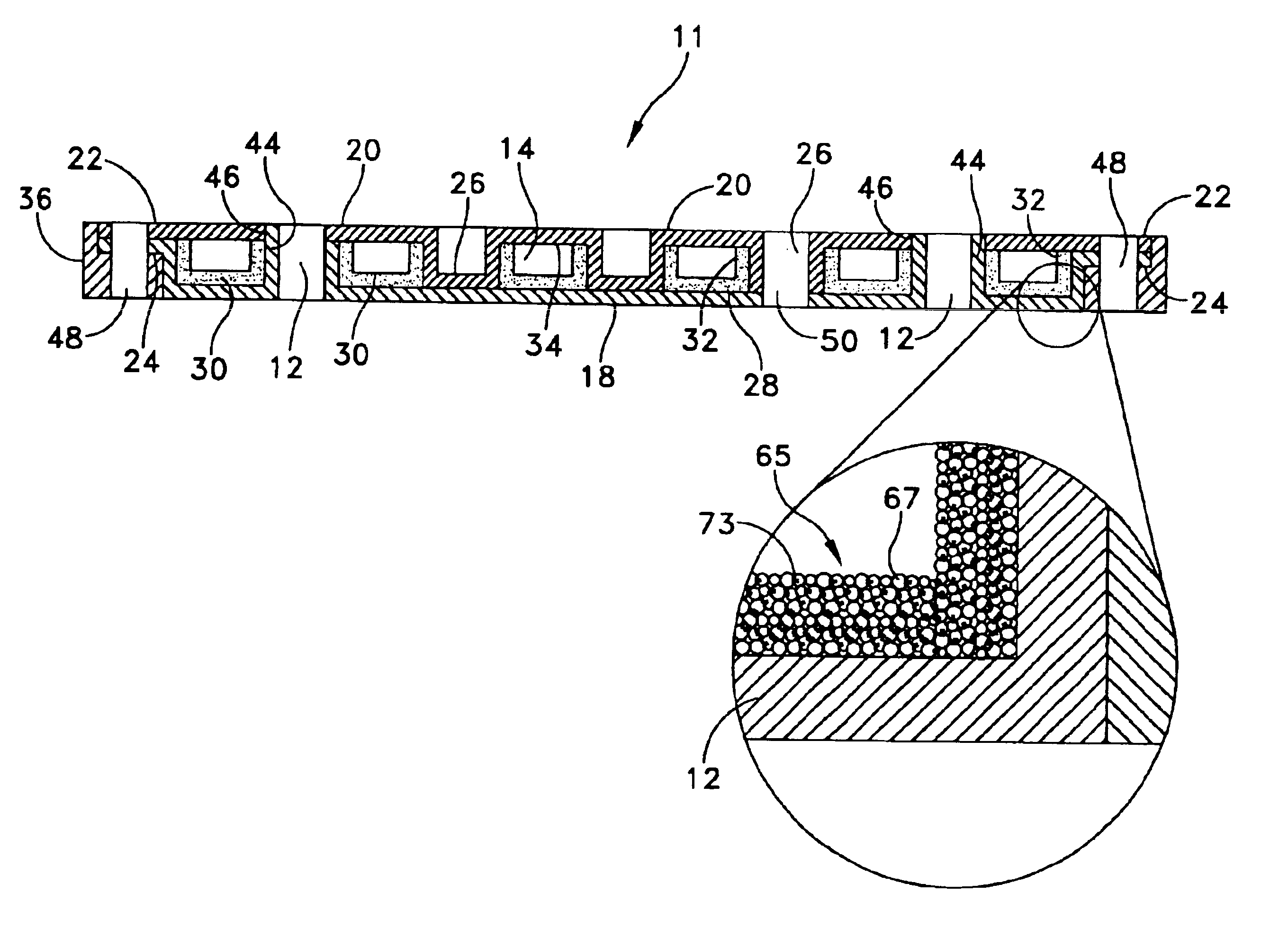
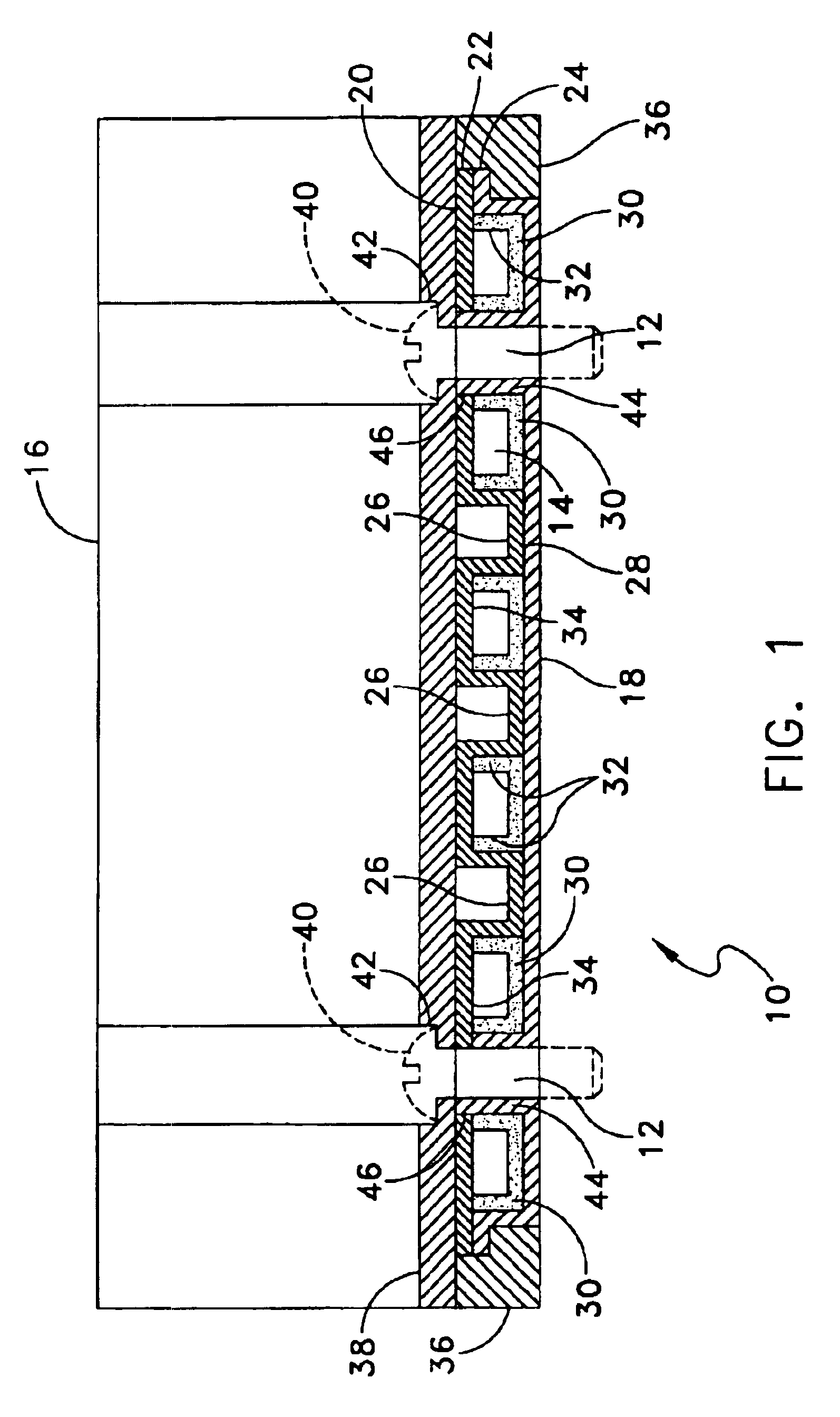
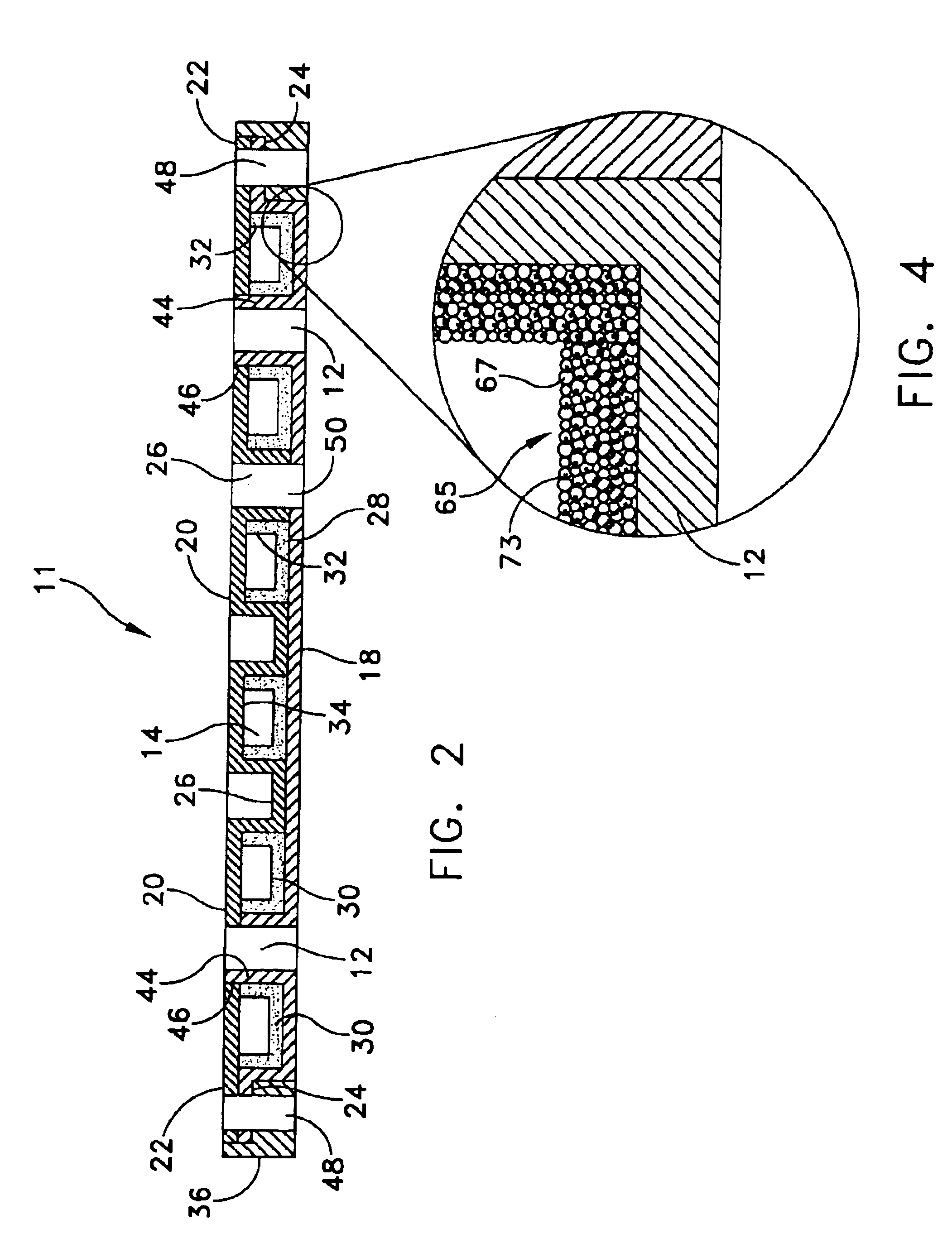
[0021]Heat pipe 10 is constructed by forming a boundary structure by sealing together two formed plates, contact plate 18 and cover plate 20. Contact plate 18 and cover plate 20 are sealed together at their peripheral lips 22 and 24 by conventional means, such as soldering or brazing, to form heat pipe 10. Heat pipe 10 is then evacuated to remove all non-condensible gases and a suitable quantity of heat transfer fluid is placed within it. This is the conventional method of constructing a heat pipe, and is well understood in the art of heat pipes.

[0022]The interior of heat pipe 10 is, however, constructed unconventionally. While contact plate 18 is essentially flat with the exception of peripheral lip 24, cover plate 20 includes multiple depressions 26. Depressions 26 are formed and dimensioned so that, when contact plate 18 and cover plate 20 are joined, the flat portions of depressions 26 are in contact with inner surface 28 of contact plate 18. Depressions 26 thereby assure that t...


PUM

PropertyMeasurementUnit
melting pointaaaaaaaaaa
thicknessaaaaaaaaaa
thicknessaaaaaaaaaa

Abstract

A heat pipe with superior heat transfer between the heat pipe and the heat source and heat sink is provided. The heat pipe is held tightly against the heat source by mounting holes which penetrate the structure of the heat pipe but are sealed off from the vapor chamber because they each are located within a sealed structure such as a pillar or the solid layers of the casing surrounding the vapor chamber. Another feature of the heat pipe is the use of a plurality of particles joined together by a brazing compound such that fillets of the brazing compound are formed between adjacent ones of the plurality of particles so as to form a network of capillary passageways between the particles of the wick.

Description

CROSS-REFERENCE TO RELATED APPLICATIONS[0001]This application is a continuation-in-part of U.S. patent application Ser. No. 09 / 852,322, filed May 9, 2001, which is a continuation of U.S. patent application Ser. No. 09 / 310,397, filed May 12, 1999, now U.S. Pat. No. 6,302,192.BACKGROUND OF THE INVENTION[0002]This invention relates generally to active solid state devices, and more specifically to a heat pipe for cooling an integrated circuit chip, with the heat pipe designed to be held in direct contact with the integrated circuit.[0003]As integrated circuit chips decrease in size and increase in power, the required heat sinks and heat spreaders have grown to be larger than the chips. Heat sinks are most effective when there is a uniform heat flux applied over the entire heat input surface. When a heat sink with a large heat input surface is attached to a heat source of much smaller contact area, there is significant resistance to the flow of heat along the heat input surface of the he...

Claims


Application Information

Patent Timeline
Patent Type & Authority Patents(United States)
IPC IPC(8): F28D15/04F28D15/02H01L23/427H01L23/34H05K7/20B22F3/11C22C1/04F28D15/00F28F7/00H01L23/40
CPCB22F3/11F28D15/0233F28D15/046H01L23/4006H01L23/427B22F2999/00F28F2275/04H01L2924/0002B22F3/1035H01L2924/00
Inventor DUSSINGER, PETER M.MYERS, THOMAS L.ROSENFELD, JOHN H.MINNERLY, KENNETH L.
Owner AAVID THERMALLOY LLV
Why Eureka
Try Eureka