Bearing mounting flange having flexibility pocket

Inactive Publication Date: 2005-05-24
CATERPILLAR INC
View PDF14 Cites 17 Cited by
  • Summary
  • Abstract
  • Description
  • Claims
  • Application Information

AI Technical Summary

Benefits of technology

[0009]A mounting flange for housing a bearing cup of a roller bearing is disclosed. The mounting flange includes a recess sized to receive the bearing cup. A radial wall is defined by the recess and an outer periphery of the mounting flange. The radial wall includes at least one region of greater radial thickness than the radial thicknes

Problems solved by technology

It is generally accepted that fatigue failure of rolling element bearings occurs as a result of progressive flaking or pitting of the surfaces of the rolling elements and the surfaces of corresponding bearing races.
This flaking and/or pitting causes the rolling elements to seize, thereby generating intense heat, pressure, and friction.
However, the mounting flange is typically not designed to uniformly, elastically deform during installation of the bearing cup.
Accordingly, non-uniform strain is applied to the bearing cup when the cup is press fit into a mounting flange having an inconsistent shape.

Method used


Image

  • Bearing mounting flange having flexibility pocket
  • Bearing mounting flange having flexibility pocket
  • Bearing mounting flange having flexibility pocket

Examples


Example

[0017]Embodiments of the mounting flange are now described with reference to the figures wherein like reference numbers indicate like elements. Also in the figures, the left most digit of each reference number corresponds to the figure in which the reference number is first used.

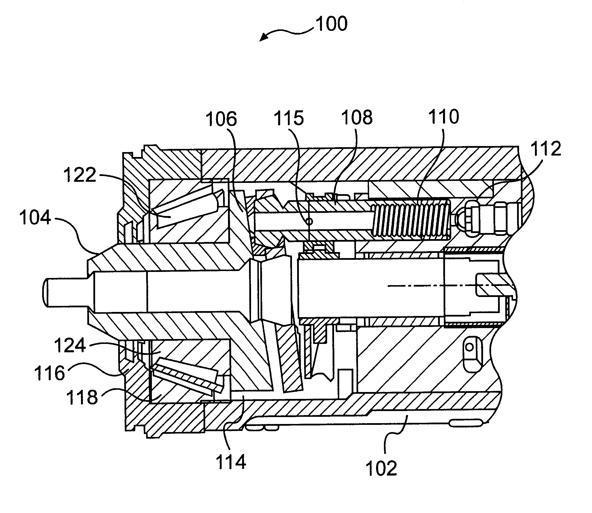
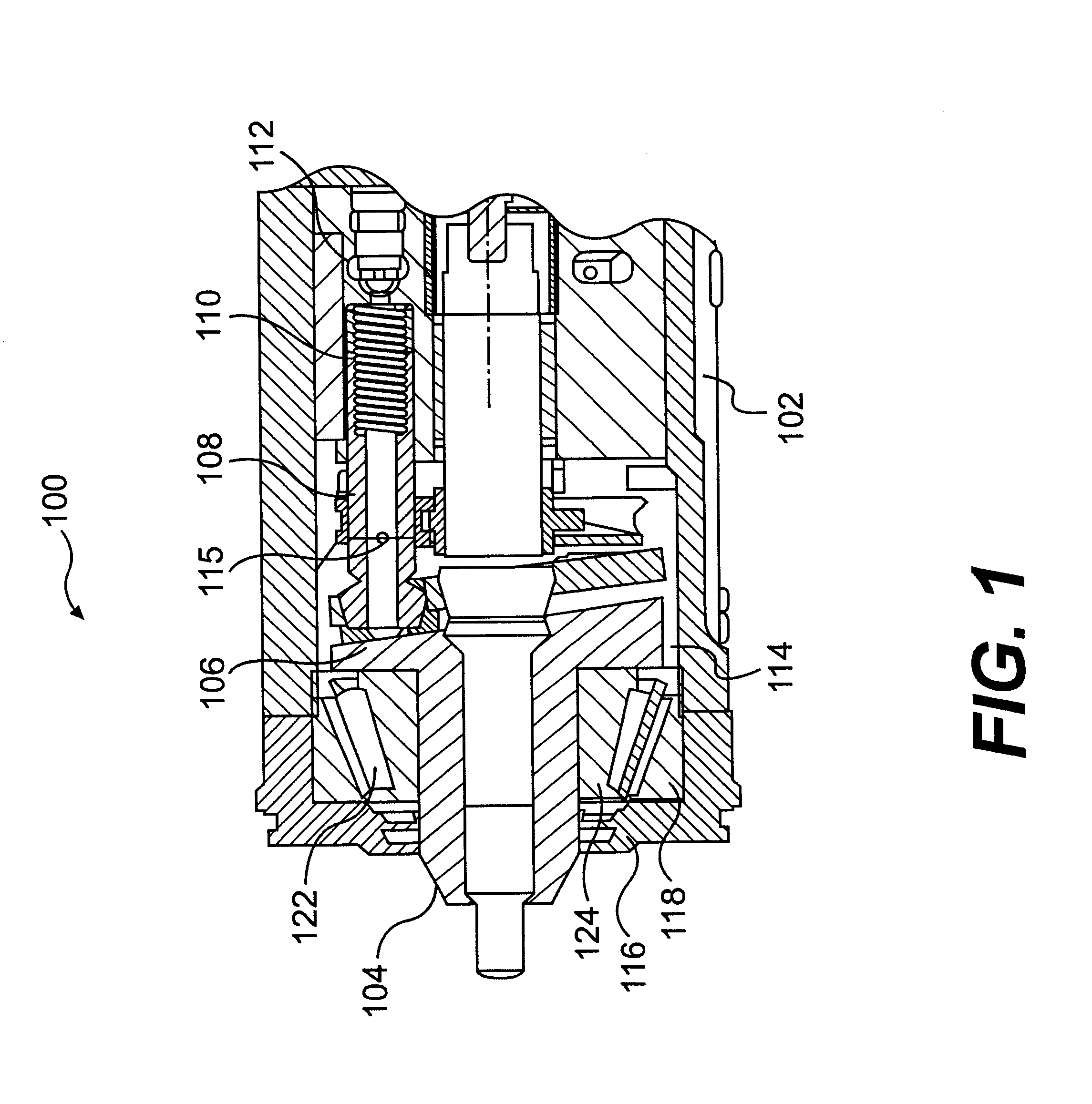
[0018]Referring to FIG. 1, a fixed-displacement, variable-delivery hydraulic pump 100 is shown. However, pump 100 could be another type of pump known to those skilled in the art. Pump 100 could be a pump used in a hydraulically-actuated, electronically-controlled unit injector (HEUI) fuel system. Pump 100 includes a housing 102 containing various components. Within pump housing 102 is an assembly including a rotating shaft 104 that is coupled directly to the output of an engine via a gear drive mechanism or other means, such that the rotation rate of shaft 104 is directly proportional to the drive shaft of the engine. A fixed angle swash plate 106 is attached to shaft 104. The rotation of swash plate 106 cau...


PUM


Abstract

A mounting flange for housing a bearing cup of a roller bearing is disclosed. The mounting flange includes a recess sized to receive the bearing cup. A radial wall is defined by the recess and an outer periphery of the mounting flange. The radial wall includes at least one region of greater radial thickness than the radial thickness at another region. The at least one region of radial thickness defines at least one ear. The mounting flange also includes at least one flexibility pocket in the at least one ear. The flexibility pocket is configured to provide substantially uniform, radial deformation to the mounting flange when the bearing cup is fit into the recess.

Description

TECHNICAL FIELD[0001]This application relates generally to a mounting flange for housing a bearing cup. More particularly, the application relates to a mounting flange having flexibility pockets.BACKGROUND[0002]A bearing is a connector allowing connected members to rotate relative to each other. Often one of the members is fixed, and the bearing acts as a support for the rotating member. Bearings include rolling elements that may take many forms, but are principally classified as balls or rollers. The rollers may likewise take a variety of forms, which are principally uniform cylinders, barrels, or cones, depending upon the application.[0003]A unique feature of rolling element bearings is that their useful life typically is not determined by wear, but rather by fatigue of the operating surfaces due to repeated stresses associated with use. It is generally accepted that fatigue failure of rolling element bearings occurs as a result of progressive flaking or pitting of the surfaces of...

Claims


Application Information

Patent Timeline
IPC IPC(8): F16C35/04
CPCF16C35/04F16C19/364
Inventor TRUBNIKOV, TIMUR T.NELSON, BRYAN E.
Owner CATERPILLAR INC
Why Eureka
Try Eureka