Connectors for hollow anatomical structures and methods of use

a technology of connecting devices and hollow anatomical organs, which is applied in the field of connecting devices for hollow anatomical organs, can solve the problems of high cost, high complexity, and time-consuming surgical procedures, and achieves cost-effective implementation, simple manufacturing, and convenient use.

Inactive Publication Date: 2005-05-24
DAKOV PEPI
View PDF35 Cites 141 Cited by
  • Summary
  • Abstract
  • Description
  • Claims
  • Application Information

AI Technical Summary

Benefits of technology

[0018]It is a further object to provide connectors that are simple to manufacture, easy to use, and cost-effective to implement.

Problems solved by technology

The most important and difficult part of the work of the surgeon is to perform anastomoses of hollow anatomical organs.
The surgical procedure is time consuming and demands highly specialized skills.
This is associated with a substantial rate of complications due to ischemia in the tissues suffering from the interrupted blood supply during the procedure.
Remaining blood clots and persistent drains increase the chances for development of infections.
Subjective technical mistakes by the surgeon can result in stenosis or thrombosis of the anastomosis.
Second, the higher risk of technical failure associated with the process of manual suturing remains present as the surgeon has to close the incisional slit by multiple hand stitches.
And third, the application of circular staples is limited only to relatively large organs, such as the intestines and the stomach.
Joining of hollow anatomical organs with artificial structures is also difficult as performed by the current surgical methods.
That is particularly problematic for intestinal organs, for which there are no reliable methods for joining with artificial structures.
The walls of blood vessels cannot be inverted (as the walls of gastrointestinal organs) because this will impede the blood flow.
Everting or cuffing body organs is more difficult and time consuming to perform than inverting.
Sometimes, this is even impossible to perform sometimes when the vessels are with substantially rigid walls (such as arteries with atherosclerotic changes).
For these reasons, none of these stapling devices for blood vessels has established a practical application.
The described device has several important limitations.
This limits the application of the device only to relatively large vessels.
Direct anastomosis (without a graft) of two blood vessels cannot be accomplished.
Side-to-end anastomosis cannot be performed.
It cannot be used to anastomose the second end of the graft because the mandrel cannot be withdrawn after the first end is joined.
This is a major practical limitation of the described apparatus and method.
This makes difficult the insertion of the staple apparatus into the vessel.
As explained above, this is an important limitation for the practical application of the described apparatus and method.
Compressing body organs between rigid connectors is associated with a very high risk of serious complication.
Applying a constant pressure on a substantially large area of body tissues produces adverse changes in the tissues.
This results in a necrosis, which may lead to rupture of the anastomosed organs.
This slows the metabolism and the regeneration of the tissues.
The compressed tissues become thinner while their healing is impeded.
This may lead to a leak of the anastomosis before the tissues are healed.
On the other hand, applying a light pressure may be inadequate to join the organs in a fluid tight manner, which can manifest with an immediate leak of the anastomosis.
Because of the significant risk of serious complications, none of these rigid connectors has found practical utilization.
As it was explained above, this alone is a major limitation for the practical application of the connectors.

Method used


Image

  • Connectors for hollow anatomical structures and methods of use
  • Connectors for hollow anatomical structures and methods of use
  • Connectors for hollow anatomical structures and methods of use

Examples


Embodiment Construction

[0063]According to the present invention, I have developed a connector for attachment to hollow anatomical structures in a sufficiently fast, easy and reliable manner.

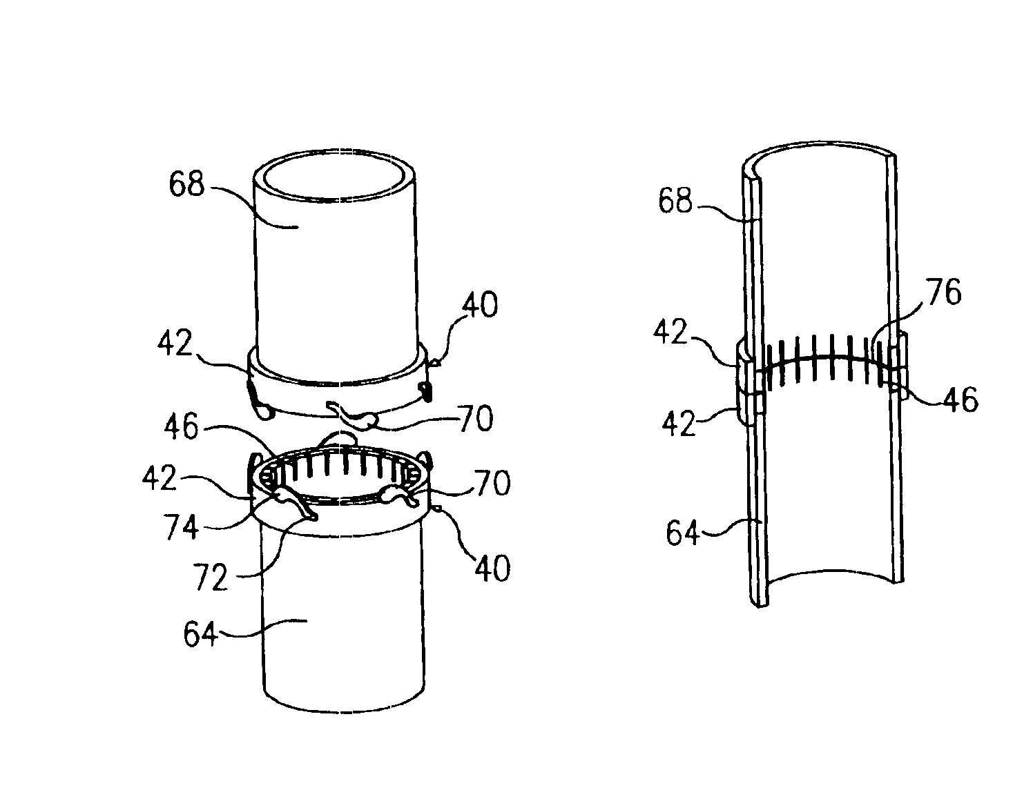
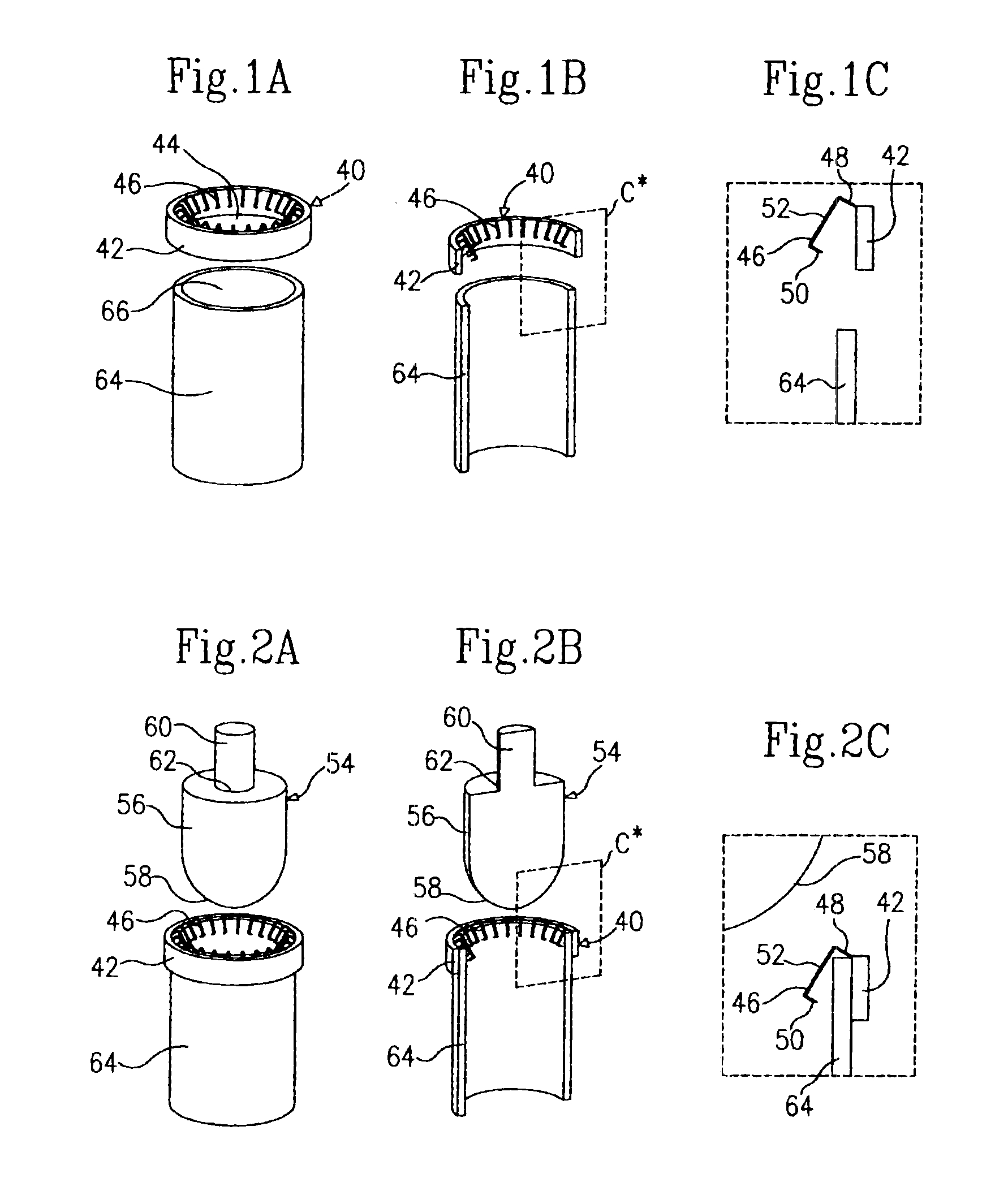
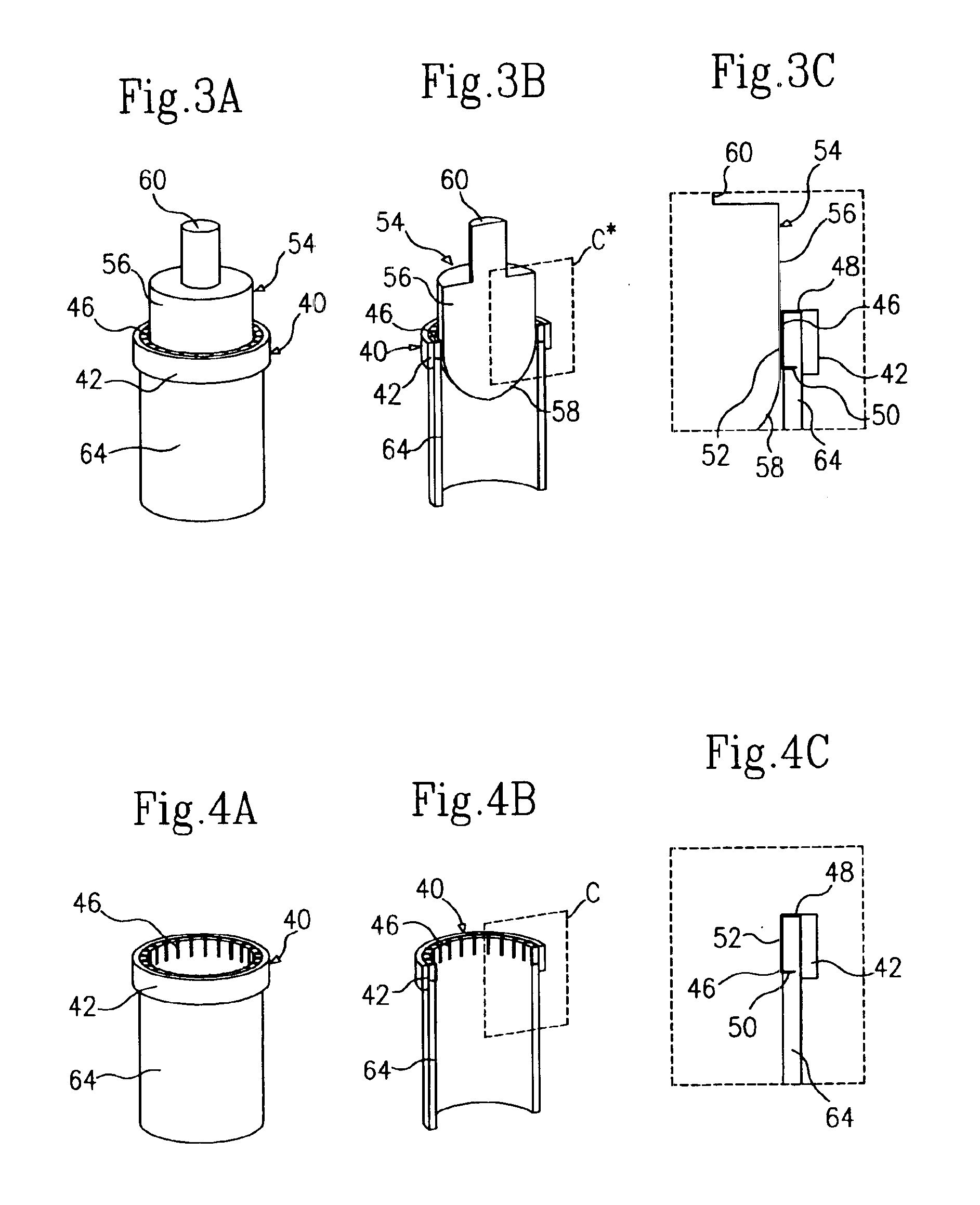
[0064]A specific preferred embodiment of an end connector and a method for attaching the connector to an end of a hollow tubular organ are shown in FIGS. 1A through 4C. For better visualization and understanding, the elements are shown in different views. They are shown in perspective views in FIGS. A. The same elements crosscut in half are shown in the same perspective views in FIGS. B. Portions of them, as defined by windows C* in FIGS. B, are shown magnified in schematic views in FIGS. C. Performing an end-to-end anastomosis of two hollow tubular organs attached with end connectors is shown in perspective views in FIGS. 5 through 7A. The end-to-end anastomosis crosscut in half is shown in a perspective view in FIG. 7B.

[0065]An end connector 40 is shown above an end-opening 66 of a hollow tubular organ 64 in FIGS. 1A...


PUM


Abstract

The connector consists of an annular rigid body conformed to an outer surface around a wall-opening of a hollow anatomical structure and holding means that keep the hollow structure adjoined internally to the annular body, wherein a union of the annular body with another annular body of another connector attached to another hollow structure forms an inner fluidproof surface that surrounds the abutted cut-edges of the wall-openings of the approximated two hollow structures. Different embodiments of end connectors and side connectors in divisible or indivisible unions are provided for end-to-end and side-to-end anastomoses of various hollow structures.

Description

[0001]This is a continuation-in-part application of U.S. patent application Ser. No. 09 / 479,792 from Jan. 8, 2000, now U.S. Pat. No. 6,254,618 which is a continuation-in-part of U.S. patent application Ser. No. 08 / 858,275 from May 19, 1997 now a U.S. Pat. No. 6,030,392 from Feb. 29, 2000.FIELD OF THE INVENTION[0002]This invention pertains to devices for joining hollow anatomical structures and more specifically to connectors for hollow anatomical structures.BACKGROUND OF THE INVENTION[0003]The most important and difficult part of the work of the surgeon is to perform anastomoses of hollow anatomical organs. At the end of the twentieth century, most of the surgical anastomoses are still performed in same way as hundred years ago—by manual suturing.[0004]Blood vessels are anastomosed by multiple manually placed stitches. The surgical procedure is time consuming and demands highly specialized skills. This is associated with a substantial rate of complications due to ischemia in the tis...

Claims


Application Information

Patent Timeline
Patent Type & Authority Patents(United States)
IPC IPC(8): A61B17/11A61B17/03A61B17/115A61B17/064
CPCA61B17/11A61B17/115A61B17/1152A61B17/0643A61B2017/1132A61B2017/00243A61B2017/1107
Inventor DAKOV, PEPI
Owner DAKOV PEPI
Why Eureka
Try Eureka