
High-power ultrasound generator and use in chemical reactions

a generator and high-power technology, applied in generators/motors, device details, mechanical vibration separation, etc., can solve the problems of limited success in using ultrasound for large-scale chemical processes, low frequency achievable by magnetostriction drives, and general limited energy output of ultrasonic generators

Inactive Publication Date: 2005-05-24
NOKIA CORP +1
View PDF17 Cites 38 Cited by
  • Summary
  • Abstract
  • Description
  • Claims
  • Application Information

AI Technical Summary

Benefits of technology

[0008]This invention thus resides in an ultrasonic vibration generator as well as a continuous-flow reactor which incorporates the ultrasonic vibration generator, and also in a method for performing a chemical reaction with the assistance of ultrasound by passing a reaction medium in liquid form through a flow-through reactor that incorporates the ultrasonic vibration generator. This invention is useful in any chemical reaction whose yield and / or reaction rate can be enhanced by ultrasound, and is particularly useful in the desulfurization of crude oil and crude oil fractions, in processes disclosed in commonly owned U.S. Pat. No. 6,402,939 (issued Jun. 11, 2002), U.S. Pat. No. 6,500,219 (issued Dec. 31, 2002), U.S. Published Patent Application No. US 2003-0051988 A1 (published Mar. 20, 2003), U.S. patent application Ser. No. 10 / 279,218 (filed Oct. 23, 2002), and U.S. patent application Ser. No. 10 / 326,356 (filed Dec. 20, 2002). All patents, patent applications, and publications in general that are cited in this specification are incorporated herein by reference in their entirety for all legal purposes that are capable of being served thereby.

Problems solved by technology

Ultrasound generators are generally of limited energy output due to the power needed to drive the vibrations and the heat generated by ultrasonic transducers.
Because of these limitations, the use of ultrasound for large-scale chemical processes has met with limited success.
One means of achieving ultrasonic vibrations at a relatively high power is by the use of magnetostriction-driven ultrasound transducers, but frequencies attainable by magnetostriction drives are still only moderate in magnitude.
These systems are not suitable for high-throughput reactions where a high reaction yield is required.

Method used


Image

  • High-power ultrasound generator and use in chemical reactions
  • High-power ultrasound generator and use in chemical reactions
  • High-power ultrasound generator and use in chemical reactions

Examples


examples

[0031]This example illustrates the use of an ultrasound generator in accordance with the present invention in the treatment by crude oil.

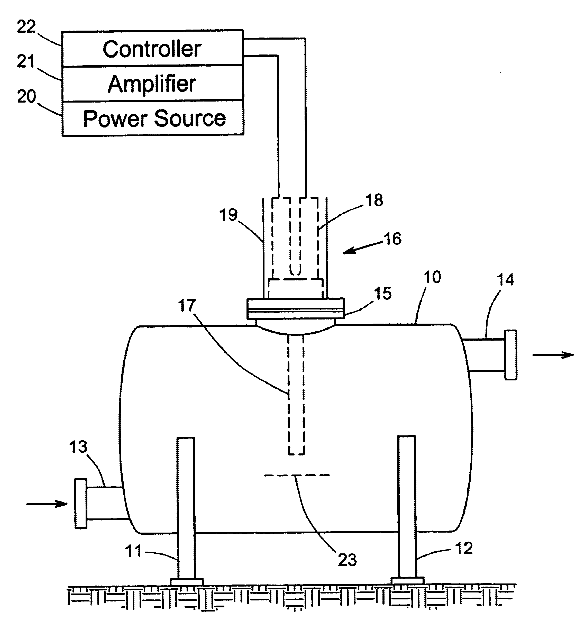
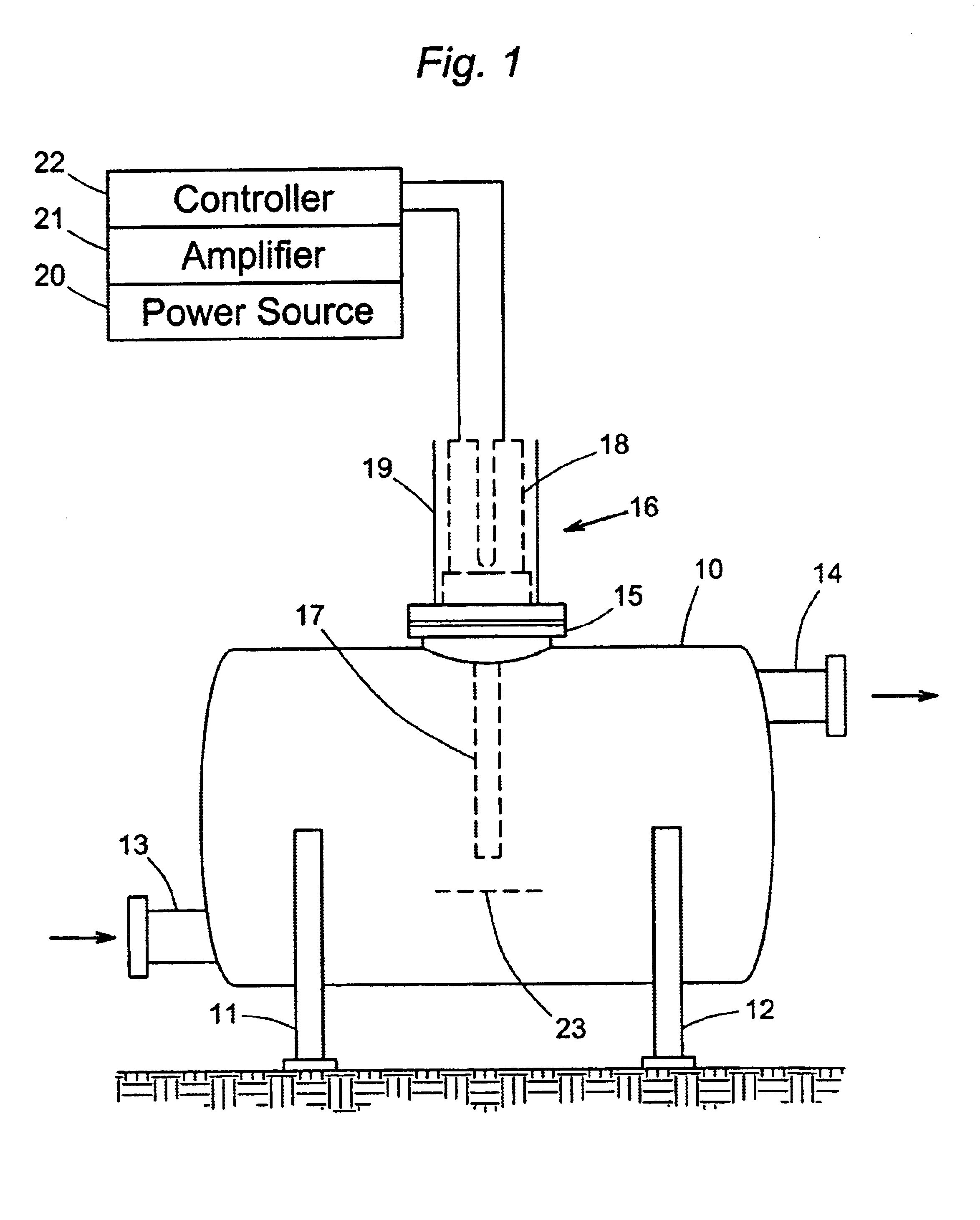
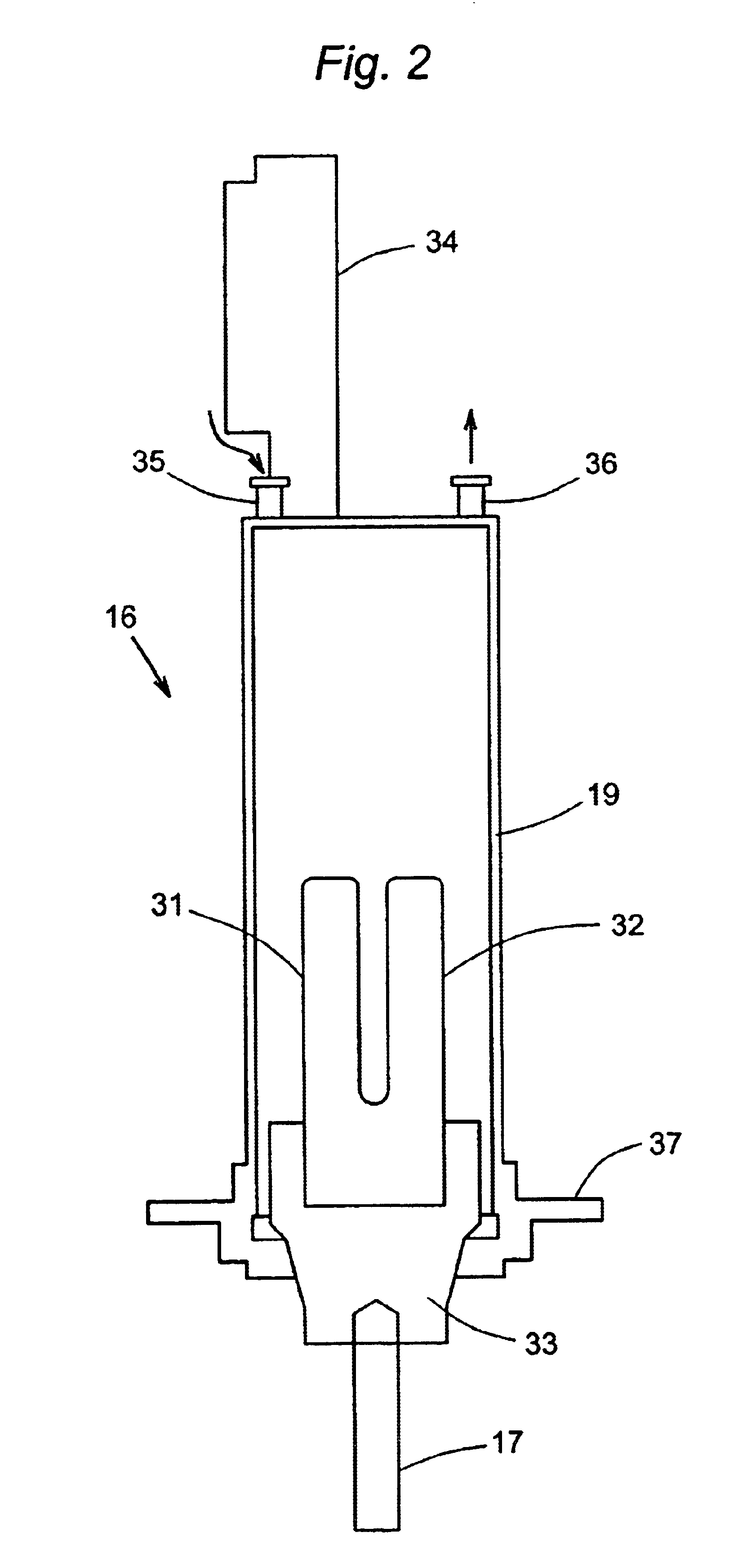
[0032]A reactor having the configuration shown in the Figures with a diameter of 8 inches (20 cm) and a length of 12 inches (30 cm) was used, with inlet and outlet ports having diameters of approximately 2 inches (5 cm), an ultrasound generator with a solid aluminum horn measuring 5.5 inches (14.0 cm) in length and 3.75 inches (9.5 cm) in diameter. The drive and sensing magnets were made from plates of PERMENDUR® (Hiperco Alloy 50A), each prong measuring 5.8 inches (14.8 cm) in length (total length, including crossbar, of 9 inches or 23 cm), 1.36 inch (2.4 cm) in width, and 0.14 inch (0.37 cm) in thickness, with seventeen such plates forming the drive prongs and three such plates forming the sensing prongs. The plates were annealed at approximately 1,600° F. (870° C.) for several hours, then cooled in a vacuum, prior to bonding. The block was annea...


PUM


Abstract

Ultrasound for use in promoting a chemical reaction is generated by an electromagnet formed from a pair of magnetostrictive prongs wound with coils that are oriented to produce an oscillating magnetostrictive force when an oscillating voltage is applied, in conjunction with a sensing electromagnet of magnetostrictive material that is arranged to receive the vibrations generated by the driving electromagnet and produce internal magnetic field changes due to the reverse magnetostrictive effect. These field changes generate voltages that are representative of the amplitude of the oscillating magnetostrictive force. The generated voltage is compared to a target value in a control circuit that adjusts the applied oscillating voltage accordingly. The oscillations in the prongs of the electromagnet are transmitted to an ultrasonic horn that is immersed in the reaction medium to provide direct contact with the reaction mixture.

Description

BACKGROUND OF THE INVENTION[0001]1. Field of the Invention[0002]This invention resides in the field of process equipment used in the treatment of materials in liquid media by ultrasound.[0003]2. Description of the Prior Art[0004]The use of ultrasound for driving chemical reactions is well known. Examples of publications that describe chemical uses of ultrasound are Suslick, K. S., Science, vol. 247, p. 1439 (1990), and Mason, T. J., Practical Sonochemistry, A User's Guide to Applications in Chemistry and Chemical Engineering, Ellis Norwood Publishers, West Sussex, England (1991). Of the various sonicating systems that have been developed, those known as “probe”-type systems include an ultrasonic transducer that generates ultrasonic energy and transmits that energy to an ultrasonic horn for amplification.[0005]Ultrasound generators are generally of limited energy output due to the power needed to drive the vibrations and the heat generated by ultrasonic transducers. Because of these ...

Claims


Application Information

Patent Timeline
Patent Type & Authority Patents(United States)
IPC IPC(8): B06B1/08B06B3/00B06B1/02H10N30/20H10N35/00H10N35/80
CPCB06B1/0261B06B3/00B06B1/08B01J19/10H10N35/80H10N35/00
Inventor GUNNERMAN, RUDOLF W.RICHMAN, CHARLES I.
Owner NOKIA CORP
Learn More