

Arbitrary function generating circuit using a simple operational element and an encryption method thereof
a technology of generating circuit and operation element, applied in the field of generating circuit using arbitrary function operation element and encryption method thereof, can solve the problems of rarely using analog calculation method and rarely using analog arithmetic circuit anymore, and achieve the effect of simple circuit elements
- Summary
- Abstract
- Description
- Claims
- Application Information
AI Technical Summary
Benefits of technology
Problems solved by technology
Method used
Image

Examples
first embodiment
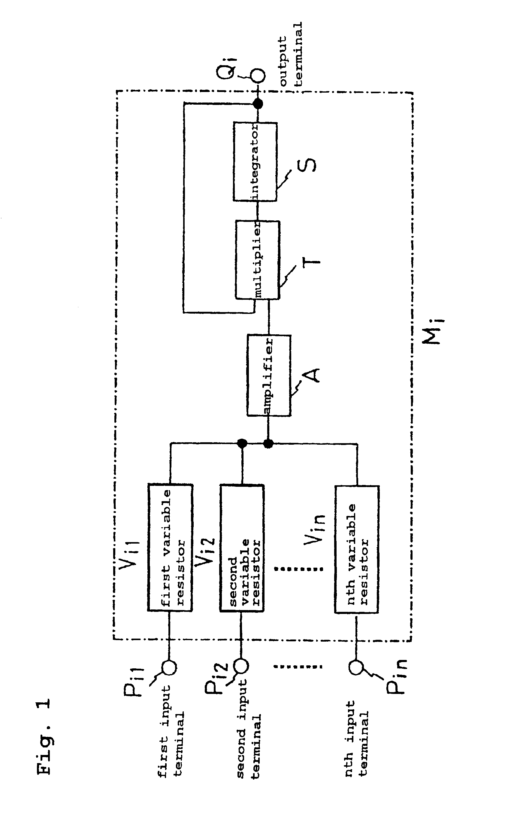
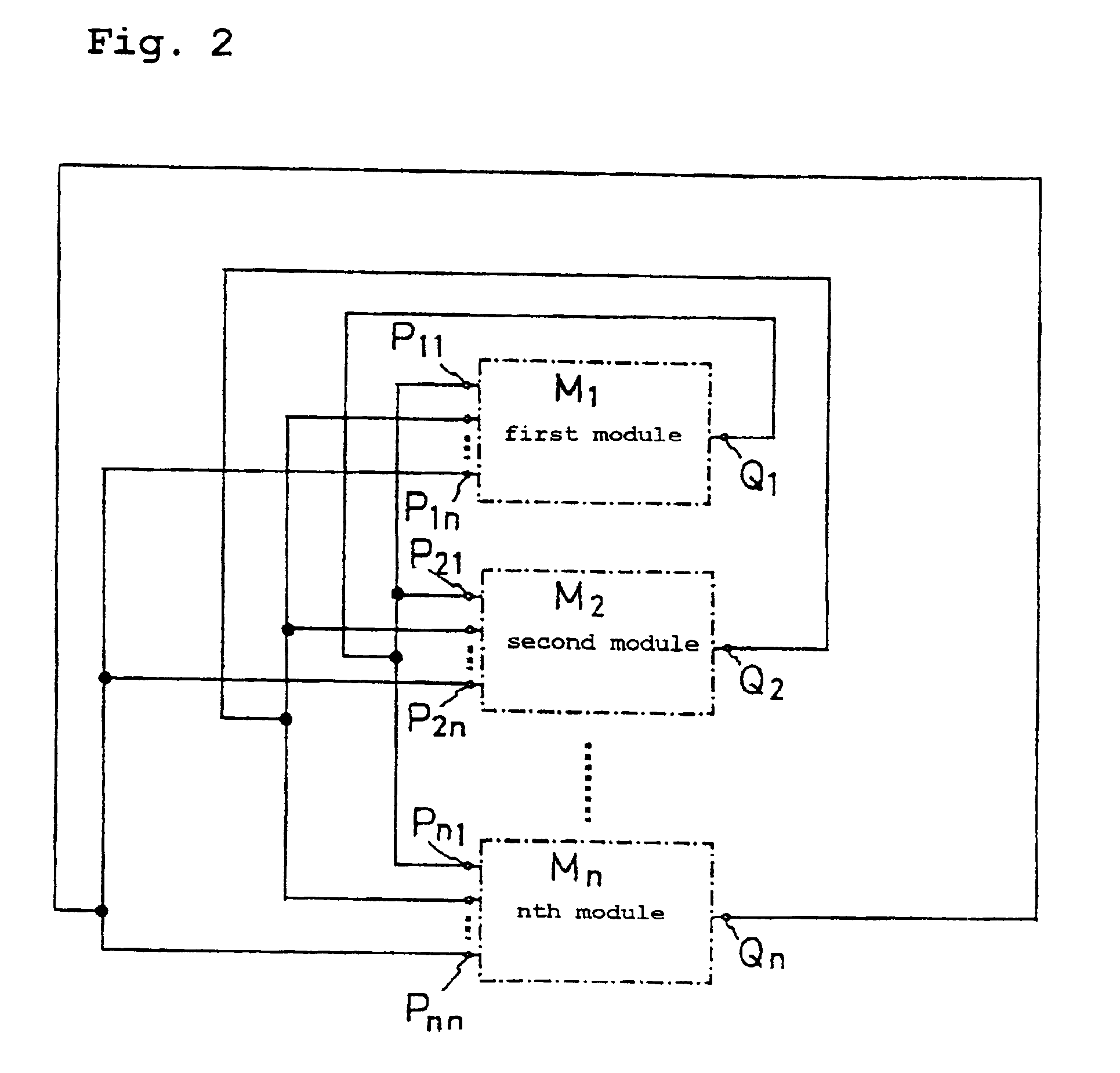
[0035]An arbitrary function generating circuit according to preferred embodiments of the present invention will be described while referring to the accompanying drawings. A first embodiment will be described with reference to FIGS. 1 and 2. FIG. 2 shows an overall schematic for an arithmetic circuit of a generalized Lotka-Volterra equation, while FIG. 1 is a block diagram of a module in that circuit.
[0036]Here, Mi represents an arbitrary module. The arithmetic circuit is configured of n number of modules. Each module has n number of input terminals Pij and one output terminal Q1.
[0037]The arithmetic circuit further comprises a first connecting wire for connecting the output terminal Q1 of the first module M1 to the first input terminals P11, P21, . . . , Pn1 of each module; a second connecting wire for connecting the output terminal Q2 of the second module M2 to the second input terminals P12, P22, . . . , Pn2 of each module; and continuing in this way to an nth connecting wire for ...
second embodiment
[0045]Next, the present invention will be described with reference to FIGS. 3 and 4. FIG. 4 shows the overall schematic of an arithmetic circuit for the generalized Lotka-Volterra equation, while FIG. 3 is a block diagram of the circuit modules in that arithmetic circuit. Here, Ni represents an arbitrary module. The arithmetic circuit is configured of n number of modules. Each module has one input / output terminal Ri. The input / output terminal Ri for each module is connected to one signal bus line.
[0046]Each arbitrary module Ni includes a frequency synthesizer F1; a first multiplier T1 for multiplying the output from the frequency synthesizer F1 with the value input from the signal bus line via the input / output terminal Ri; a low pass filter L for removing the AC component from the value output from the first multiplier T1; a second multiplier T2 into which the output from the low pass filter L is input; an integrator S1 for integrating the output from the second multiplier T2; a con...
third embodiment
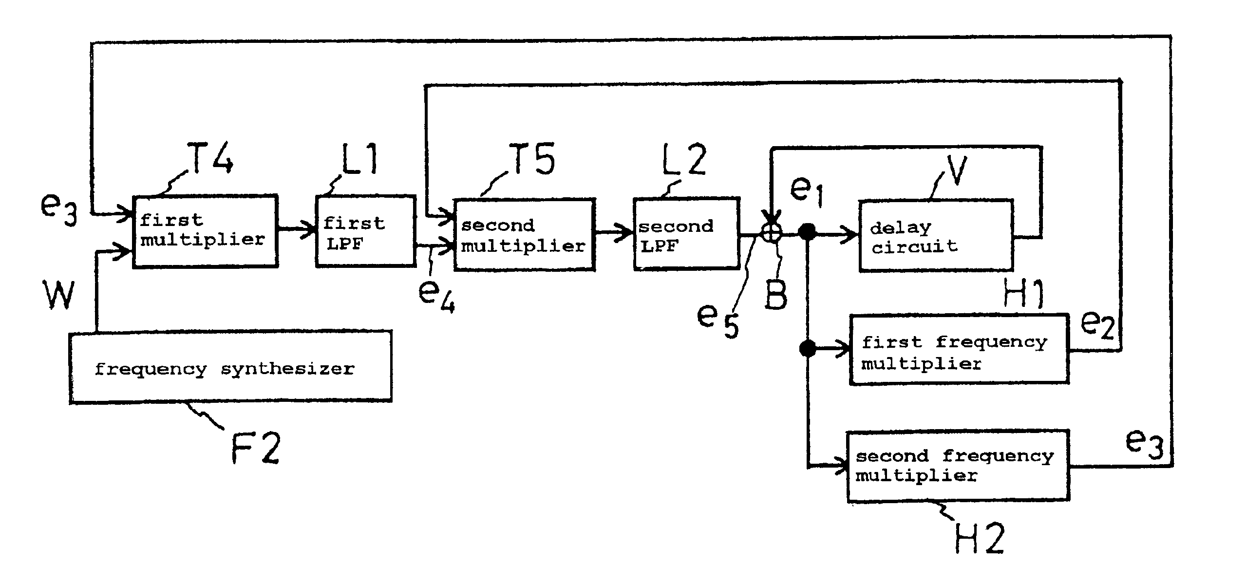
[0056]FIG. 5 shows the present invention. FIG. 5 is a block diagram showing the overall schematic of the arithmetic circuit for the generalized Lotka-Volterra equation achieved in one module.
[0057]The module comprises a frequency synthesizer F2 that outputs a value W; a first multiplier T4 that receives the output value W as one input value; a first low pass filter L1 for cutting out the first frequency component from the value output from the first multiplier T4; a second multiplier T5 that receives the value e4 output from the first low pass filter L1 as one input value; a second low pass filter L2 that removes a second frequency component lower than the first frequency component from the value output from the second multiplier T5; an adder B that receives the output value e5 as one input value; a delay circuit V that delays the output value e1 and sets the output value e1 as the second input value to the adder B; a first frequency multiplier H1 that multiplies the frequency of th...
PUM
 Abstract
Description
Claims
Application Information