Battery mounting structure for a small watercraft, and method of using same

a technology for mounting structures and watercraft, which is applied in the field of small watercraft battery mounting structures, can solve the problems of difficult to improve turning performance and a small amount of water entering the vessel, and achieve the effect of improving turning performance and minimizing the risk of water contacting the battery

Inactive Publication Date: 2005-05-31
HONDA MOTOR CO LTD
View PDF4 Cites 6 Cited by
  • Summary
  • Abstract
  • Description
  • Claims
  • Application Information

AI Technical Summary

Benefits of technology

[0013]The present invention provides a battery mounting structure for a small watercraft in which turning performance is improved, while a battery is stored in the inventive mounting structure is substantially waterproofed, so that the risk of water contacting the battery is minimized.
[0015]Consequently, the battery is disposed at the central area of the vessel body, close to the longitudinal axis thereof, and as a result, the weight balance of the batteries is substantially centralized (to place heavy parts at the center of the vessel as much as possible). As a result of this centralized weight balance, turning performance of the vessel is improved.
[0016]Since the battery is disposed on the drive shaft supporting box, the battery is located at a significantly higher level above the bottom of the vessel, and thus contact with water in the hull is minimized.
[0017]Therefore, when the vessel body is rotated to the upright position after having rolled over, the battery is significantly protected from getting wet. Therefore, waterproofing of the battery may be simplified due to decreased chances of water contact.

Problems solved by technology

During operation of the small watercraft, the vessel can overturn in the water, resulting in at least a small amount of water entering the vessel.
6(a), it is difficult to strike a weight balance and to centralize a mass (to place heavy parts at the center of the vessel as much as possible), and thus it is difficult to improve turning performance.
In addition, there is such problem that when restoring the vessel body 1 to a normal posture after having rolled over in the water, one of the batteries 4a, 4b disposed separately on the left and the right sides of the vessel body 1 comes in contact with water remaining in the vessel.

Method used


Image

  • Battery mounting structure for a small watercraft, and method of using same
  • Battery mounting structure for a small watercraft, and method of using same
  • Battery mounting structure for a small watercraft, and method of using same

Examples


Embodiment Construction

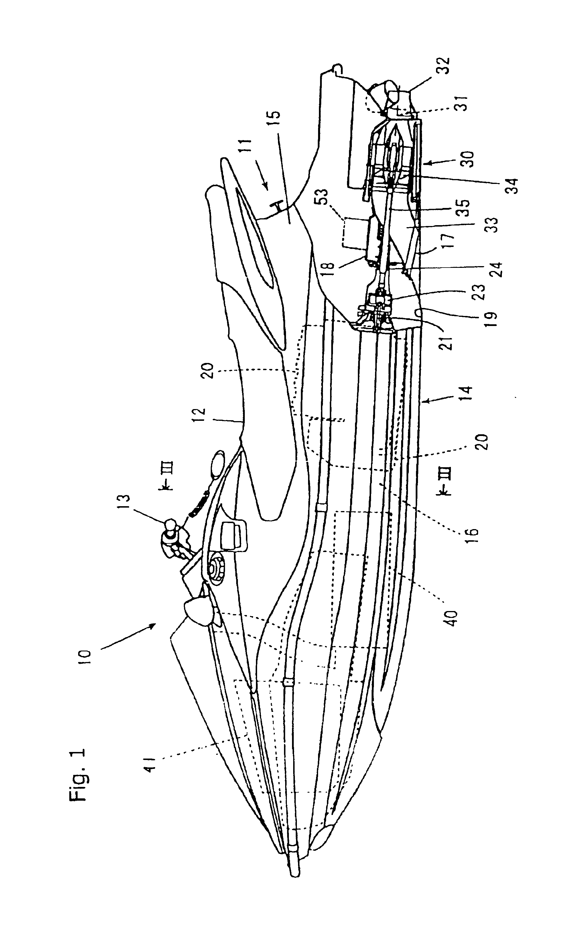
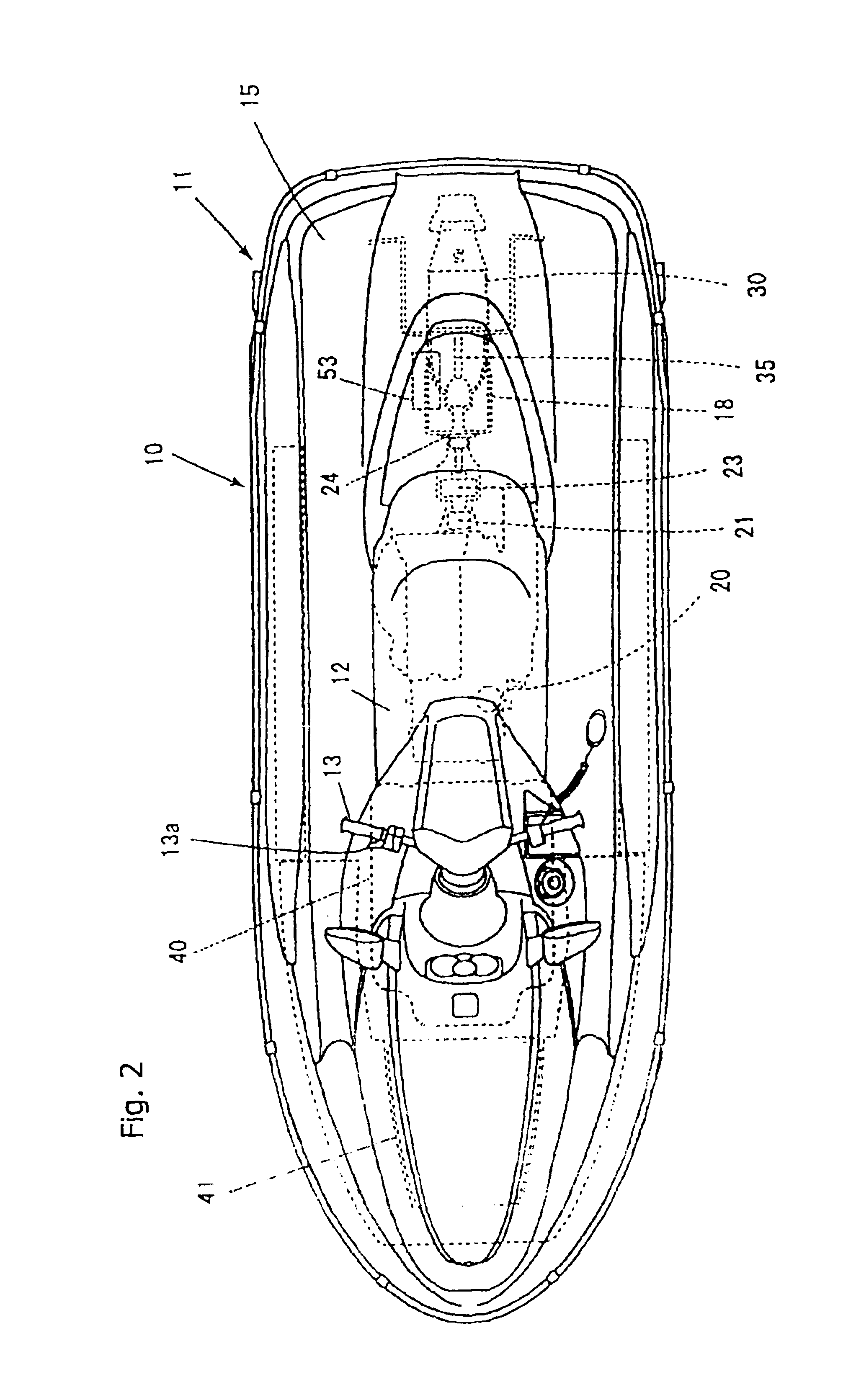
[0025]As shown in the drawings (mainly in FIG. 1), the small watercraft 10 is a saddle riding type small watercraft in which an operator is able to sit on a seat 12 of a vessel body 11, and to operate while gripping a steering handle 13 with a throttle lever incorporated therein.

[0026]The vessel body 11 is a floating structure formed by joining a hull 14 and a deck 15 for defining a space 16 inside. In the space 16, a water-cooled engine 20 is mounted at substantially the center (substantially longitudinal and lateral center) on the hull 14, and a jet pump (jet propulsion pump) 30 as propulsion means driven by the water-cooled engine 20 is mounted at the rear of the hull 14.

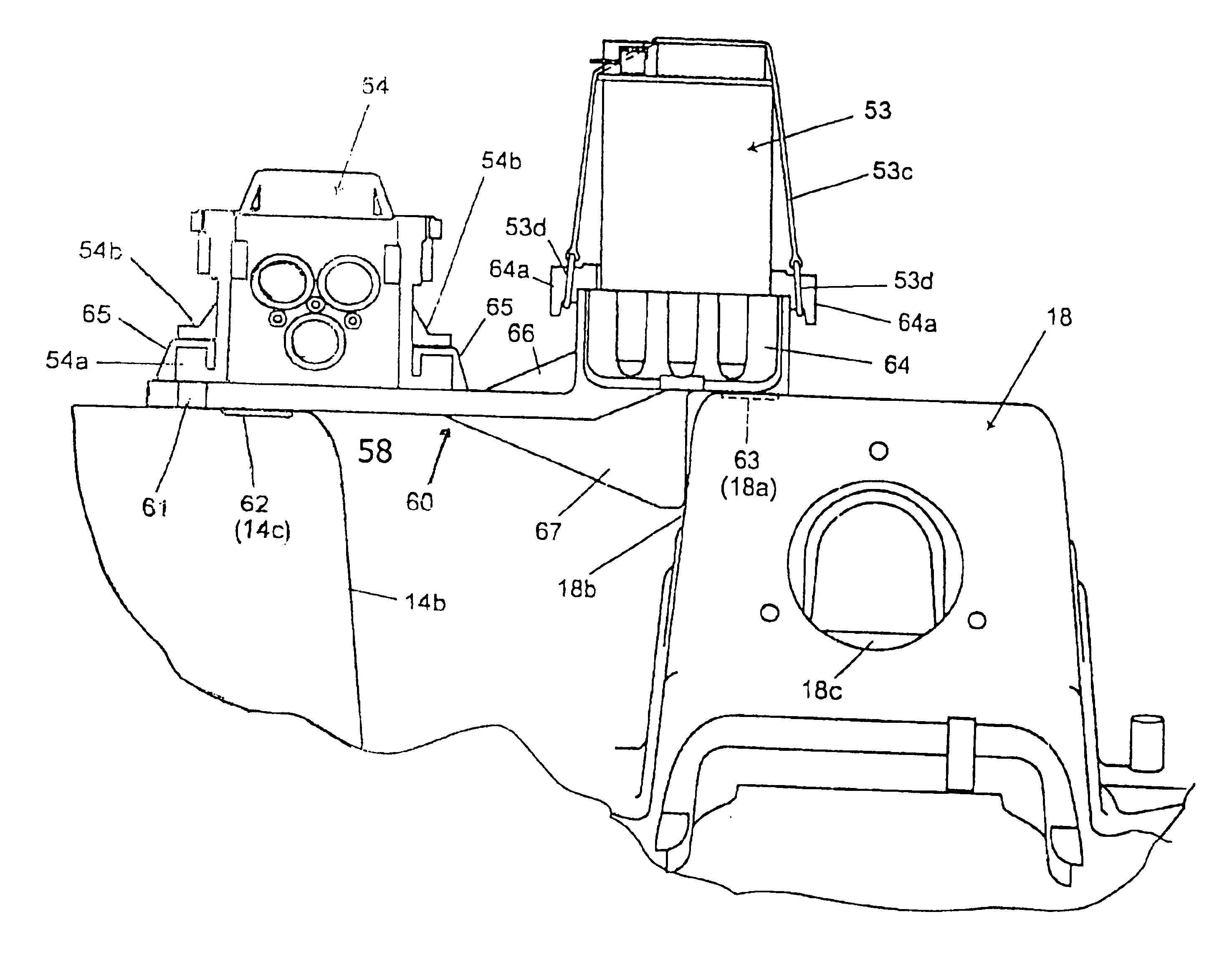
[0027]A drive shaft (more specifically, a drive shaft for an impeller 34 described below) 35 of the jet pump 30 extends rearwardly from the engine 20, and is supported at the midsection thereof by a drive shaft supporting box 18 via a bearing unit 24.

[0028]The jet pump 30 includes a channel 33 extending from a wa...


PUM


Abstract

A battery mounting structure for a small watercraft is constructed and arranged to improve turning performance of the craft and to provide waterproofing protection. A vessel body 11 includes a hull 14, constituting a lower portion of the vessel body, and a deck 15 for covering on top of the hull. An engine 20 is disposed in the vessel body 11, with a drive shaft 35 extending rearward from the engine 20 for driving a propeller 30, and a drive shaft supporting box 18 for supporting the drive shaft at the midsection thereof. The inventive mounting structure is substantially centrally located, so that the battery 53 can be disposed on the drive shaft supporting box 18.

Description

CROSS-REFERENCE TO RELATED APPLICATIONS[0001]The present application claims priority under 35 U.S.C. 119, based on Japanese patent application No. 2002-284219, filed Sep. 27, 2002.BACKGROUND OF THE INVENTION[0002]1. Field of the Invention[0003]The present invention relates to a battery mounting structure for a small watercraft. More particularly, the present invention relates to a battery mounting structure for a small watercraft which provides for waterproofing protection and improves the turning characteristics of the small watercraft.[0004]2. Description of the Background Art[0005]A personal watercraft is known as a small size craft that is constructed and arranged to glide on the surface of a sea or lake. Many jet skis and other different types of personal watercraft are known and are commercially available.[0006]In the background art, one example of a known type of battery mounting structure for a small watercraft is described in JP-A-10-194195. FIGS. 6(a) and 6(b) of the prese...

Claims


Application Information

Patent Timeline
Patent Type & Authority Patents(United States)
IPC IPC(8): B63B35/73B63B11/00B63J99/00
CPCB63B11/00B63J99/00B63B35/731B63J2003/002B63B34/10
Inventor NAKAJIMA, JUNMIURA, TAKAYOSHIFUNAYOSE, YUSUKE
Owner HONDA MOTOR CO LTD
Why Eureka
Try Eureka