Vibration-isolating bushing

a technology of vibration isolation and bushing, which is applied in the direction of shock absorbers, machine supports, transportation and packaging, etc., can solve the problems of low degree of freedom of design between the spring constant in the axially square direction and the spring constant in the prying direction, and achieves no cutting wastage, preventing an undesired rotation of the inner cylinder, and enhancing the strength of the serration

Inactive Publication Date: 2005-05-31
TOYO TIRE & RUBBER CO LTD
View PDF18 Cites 11 Cited by
  • Summary
  • Abstract
  • Description
  • Claims
  • Application Information

AI Technical Summary

Benefits of technology

[0013]With the vibration-isolating bushing of this invention, on the outer periphery of the inner cylinder there is formed the knurling, on the surface of which the annular cover as a bulge portion is provided by molding of a synthetic resin. Because of this structure, the synthetic resin intrudes within fine mesh-like furrows of the knurling and the annular cover is strongly anchored to the outer periphery of the inner cylinder. As a consequence, any displacement of the annular cover in the axial and rotational directions upon vulcanization molding of the rubber-like elastomer is prevented. Further, the knurling (knurls) can be provided by a simple method of urging a cylindrical knurling tool having on its outer periphery notches toward the workpiece under rolling and hence, the bushing is low-cost and advantageous also in an environmental aspect since no cutting wastage is produced.
[0014]In the vibration-isolating bushing according to this invention, it is preferred that the metal pipe constituting the inner cylinder be provided at least at one axial edge face with a serration and further hardened by quenching. When incorporated into a

Problems solved by technology

This renders the processing cost high and causes the product weight to increase.
Further when forging, it is difficult to make the outside diameter of the bulge portion large beyond a def

Method used


Image

  • Vibration-isolating bushing
  • Vibration-isolating bushing
  • Vibration-isolating bushing

Examples


Embodiment Construction

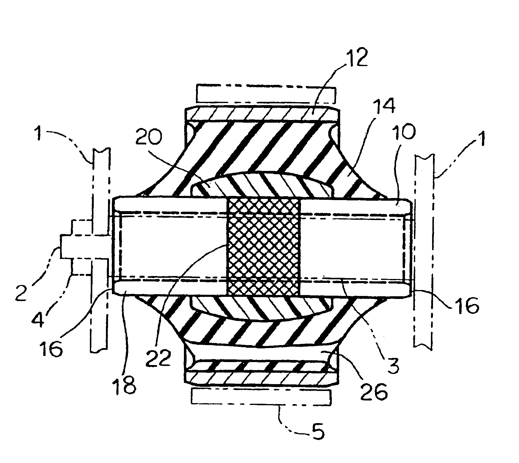
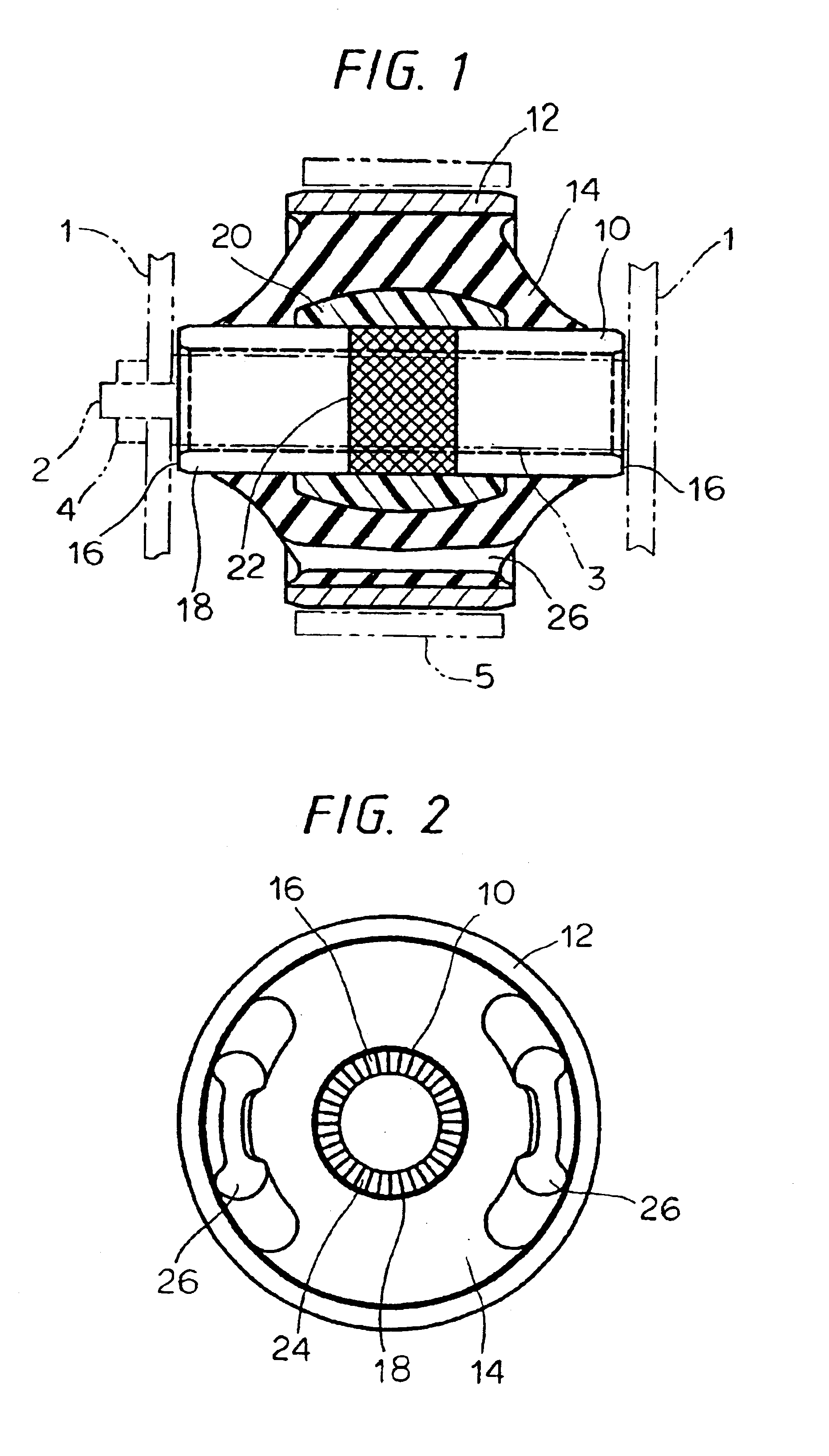
[0023]The invention will be hereinafter described by way of one embodiment with reference to the accompanying drawings. As shown in FIGS. 1 and 2, a bushing for a suspension, which is a vibration-isolating bushing relating to one embodiment of this invention, is made up of an inner cylinder 10, an outer cylinder 12 encircling the inner cylinder 10 and spaced apart a distance outwardly from the inner cylinder in an axially square direction thereof, and a ring-form rubber-like elastomer 14 interposed between the inner cylinder 10 and the outer cylinder 12. The inner cylinder 10 is secured to an attachment member 1 with its both edge faces 16, 16 pinched by means of the attachment member 1 such as a bracket by inserting a shank member 3 having a bolt 2 through the inner cylinder and fastening with a nut 4 whereas the outer cylinder 12 is press fitted in a cylinder element 5, which is the other attachment member to be secured thereto. Thereby the vibration-isolating bushing connects bot...


PUM


Abstract

In a so-called bulge type of vibration-isolating bushing wherein an annular cover made of a synthetic resin is provided as a bulge portion on an outer periphery of an axially central part of an inner cylinder, such a vibration-isolating bushing that is superior in buckling strength in the axial direction of the inner cylinder, low-cost, and advantageous in environmental aspect, while preventing any displacement of the annular cover is provided. To that end, a knurling is provided on an outer periphery of an axially central part of a metal pipe constituting the inner cylinder, preferably, together with a serration on an axial edge of the metal pipe; and the annular cover is secured to the outer periphery of the metal pipe inclusive of the knurling by molding of a synthetic resin.

Description

[0001]This is a continuation of U.S. application Ser. No. 10 / 237,301 filed Sep. 5, 2002 now abandoned, and the complete disclosure of which is hereby incorporated by this reference.BACKGROUND OF THE INVENTION[0002]1. Field of the Invention[0003]This invention relates to a vibration-isolating bushing, for example, for use in an automobile, in part of a suspension mechanism of which it is incorporated to alleviate vibrations.[0004]2. Description of the Related Art[0005]In automotive vehicles, with a view to controlling vibrations transmitted from the wheel side to the automotive body side or vibrations transmitted from the engine side to the body side, a vibration-isolating bushing is generally incorporated in part of a suspension mechanism or an engine support mechanism. One example of such vibration-isolating bushings is a so-called bulge type of vibration-isolating bushing, which is provided with a bulge portion bulging out in an axially square direction in an axially central area ...

Claims


Application Information

Patent Timeline
IPC IPC(8): F16F1/387F16F1/38
CPCF16F1/387
Inventor TAKESHITA, SEIYAWAKITA, YASUKUNI
Owner TOYO TIRE & RUBBER CO LTD
Why Eureka
Try Eureka