Method for manufacturing a turbine wheel rotor

a technology of turbine wheels and rotors, which is applied in the direction of machines/engines, liquid fuel engines, forging/pressing/hammering apparatuses, etc., can solve the problems of high cost and disadvantage of individual parts having to ensure the connection of multi-part turbine rotors, and achieve economic efficiency.

Inactive Publication Date: 2005-05-31
DAIMLER AG
View PDF25 Cites 10 Cited by
  • Summary
  • Abstract
  • Description
  • Claims
  • Application Information

AI Technical Summary

Benefits of technology

[0011]An object of the present invention is to connect the parts of multi-piece turbine wheel rotors in a simple and reliable manner.
[0019]The casting pressure required to fill the mold is reached due to the centrifugal forces occurring during centrifugal casting. It is particularly advantageous to use one or more separate ceramic shell molds in place of a common casting cluster.
[0020]Technically, the process provides the particular advantage of achieving a very rigid connection of the turbine wheel and the shaft due to the press-fit connection. Moreover, it is also possible to achieve optimum positive fit and, possibly even an integral connection.
[0021]The manufacturing process advantageously stands out compared to other joining techniques because of its economic efficiency, since the manufacture of the turbine wheel and the connection to the shaft is carried out in one step. This eliminates the need for subsequent processing steps to connect these two components. The same advantages arise on the side of the compressor wheel.

Problems solved by technology

However, insufficient strength has resulted in that compressor wheels are sometimes also milled from the solid, which is much more cost-intensive.
Apart from single-part models, multi-part turbine rotors have the disadvantage of having to ensure a suitable connection of the individual parts.

Method used


Image

  • Method for manufacturing a turbine wheel rotor
  • Method for manufacturing a turbine wheel rotor

Examples


Embodiment Construction

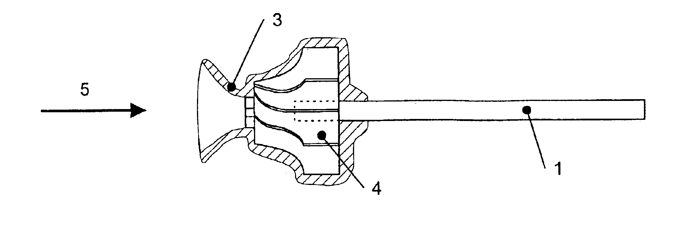
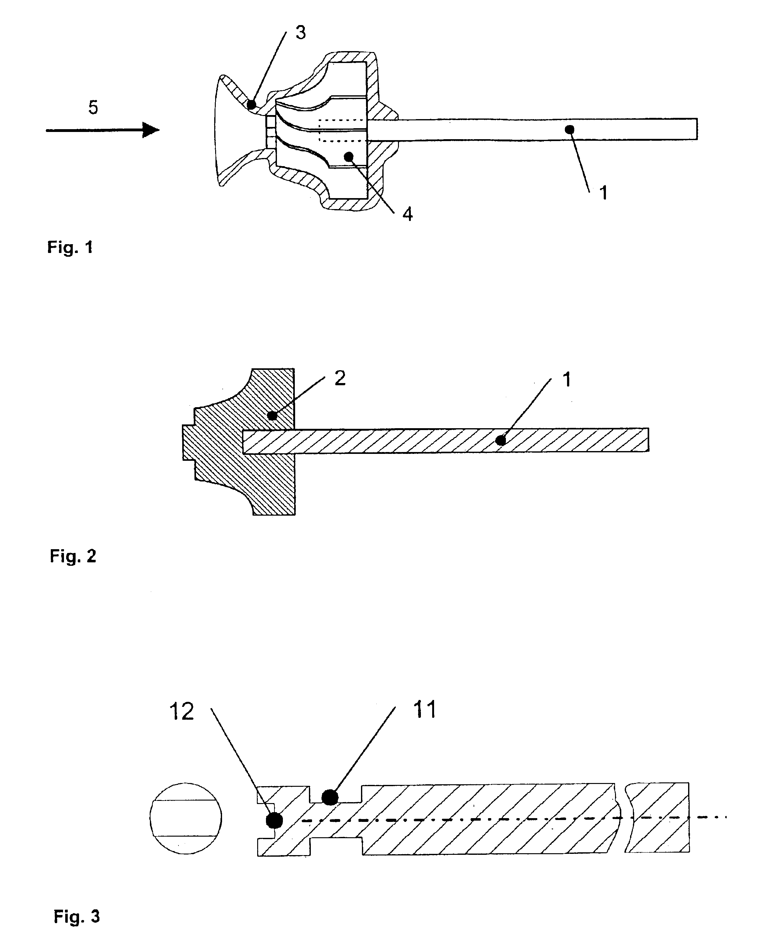
[0034]The ceramic shell mold with sprue 3, which is shown in FIG. 1, is used as a negative mold with integrated shaft 1 to manufacture the turbine wheel rotor by precision casting. For this purpose, initially, a wax model of the wheel is made using wax injection processes. Subsequently, the ceramic shell mold is built up in several dipping cycles in slurry baths and corresponding sanding operations. The wax is melted out and the shell mold is fired. The present invention proposes to insert the shaft into the mold for injection-molding the wax models and, in this manner, to injection-mold the wax model around the shaft. Also carried out are the conventional dipping and sanding operations, in which, however, not only the wax model, but also a part of or the whole shaft is surrounded by a ceramic shell mold. After melting out the wax, the shaft extends into turbine wheel cavity 4 for the turbine wheel.

[0035]The temperature control of shell mold 3 and of shaft 1 located therein is to be...


PUM

PropertyMeasurementUnit
filling pressureaaaaaaaaaa
temperatureaaaaaaaaaa
mechanical loadsaaaaaaaaaa

Abstract

A method for connecting a wheel, such as a turbine wheel or compressor wheel, in a turbine wheel rotor. The method includes providing a shaft made of steel, and pouring a casting alloy around an end of the shaft, wherein the casting alloy includes an intermetallic compound of the system TiAl. The method is particularly well-suited making a connection of the turbine wheel and the shaft of an exhaust-gas turbocharger for motor vehicles using a casting process. In addition, a turbine wheel rotor, that includes a steel shaft, a cast wheel including a casting alloy fixedly connected to an end of the shaft. The casting alloy including an intermetallic compound of the system TiAl. A connection between the cast wheel and the shaft includes at least one of a friction fit, a positive fit, and an integral connection.

Description

[0001]This application claims priority to German Patent Application 102 09 347.4-24, filed Mar. 3, 2002, which is incorporated by reference herein.BACKGROUND[0002]The present invention relates to a method for connecting a wheel, such as a turbine wheel or a compressor wheel to a shaft of a turbine wheel rotor, particularly the turbine wheel of an exhaust-gas turbocharger for motor vehicles. The present invention also relates to a turbine wheel rotor, that includes a steel shaft and a cast wheel including a casting alloy fixedly connected to an end of the shaft.[0003]Currently used turbine wheels are mostly based on Ni-based alloys. In isolated cases, turbine wheels made of TiAl have also been tested and used. According to the prior art, turbine wheels are first manufactured by precision casting or comparable methods and subsequently connected to the shaft in one or more operations. This is usually done by brazing or welding processes. Unlike the turbine wheel, the shaft is conventio...

Claims


Application Information

Patent Timeline
Patent Type & Authority Patents(United States)
IPC IPC(8): B22D17/20B22D19/00F01D5/02F01D5/04B22D19/04B22D21/02B22D21/06B22D27/09F02B39/00
CPCB22D17/2069B22D19/00B22D19/0081F01D5/025Y10T29/49321F05D2220/40F05D2230/60F05D2230/21
Inventor BAUR, HARTMUTBUSSE, PETERFLEDERSBACHER, PETERWORTBERG, DANIEL BALA
Owner DAIMLER AG
Why Eureka
Try Eureka