
Wrench manufacturing process

a manufacturing process and wrench technology, applied in the field of rolling wrench manufacturing process, can solve the problems of wrenches that are either easily deformed, cannot meet the requirements of confined rotational tubes, and the conventional manufacturing process of ordinary wrenches is not suitable for special purposes, so as to facilitate subsequent processing, improve structural toughness, and soften the roughcast

Inactive Publication Date: 2005-05-31
HSIEN CHIN CHING
View PDF3 Cites 22 Cited by
  • Summary
  • Abstract
  • Description
  • Claims
  • Application Information

AI Technical Summary

Benefits of technology

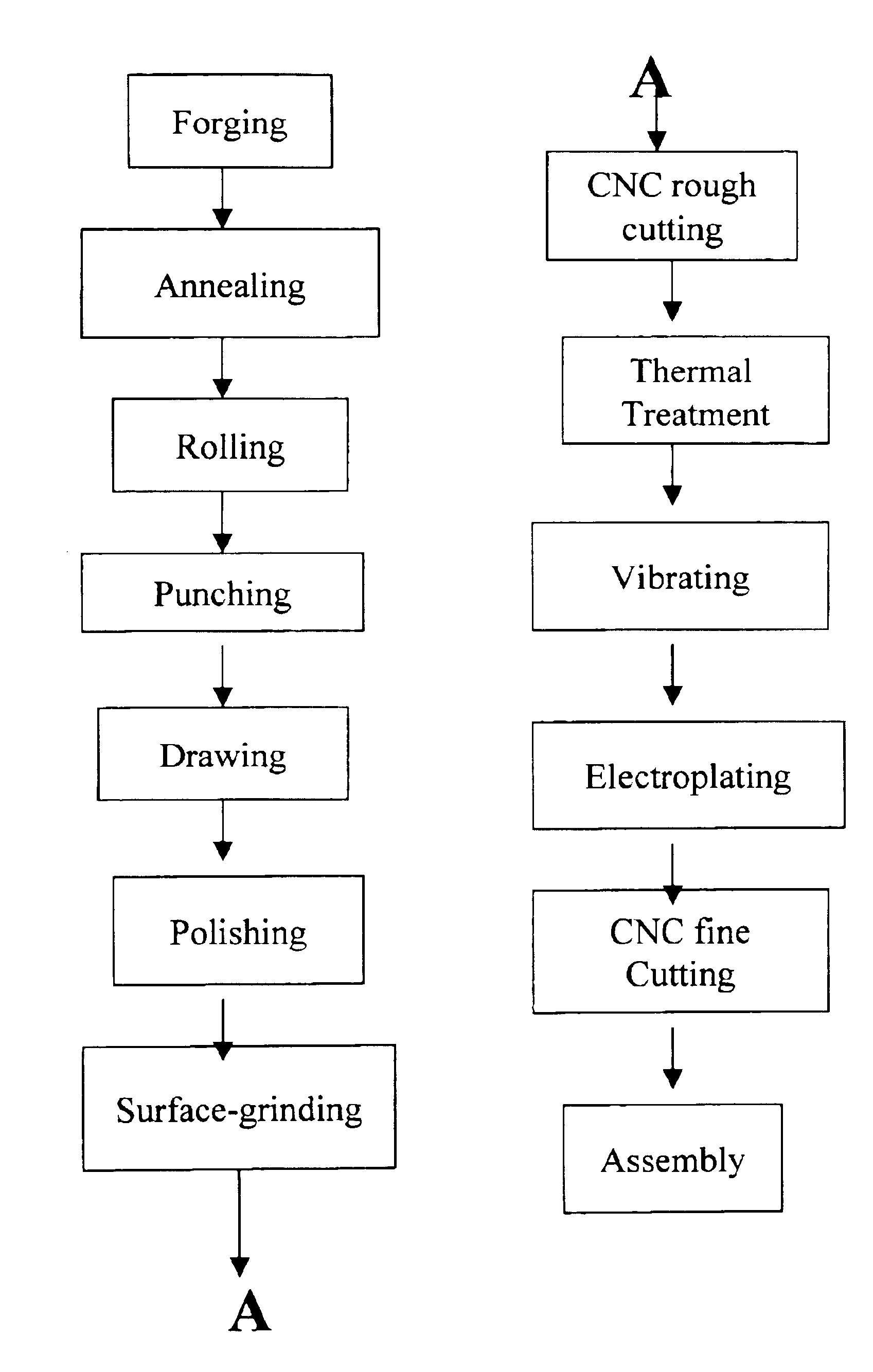
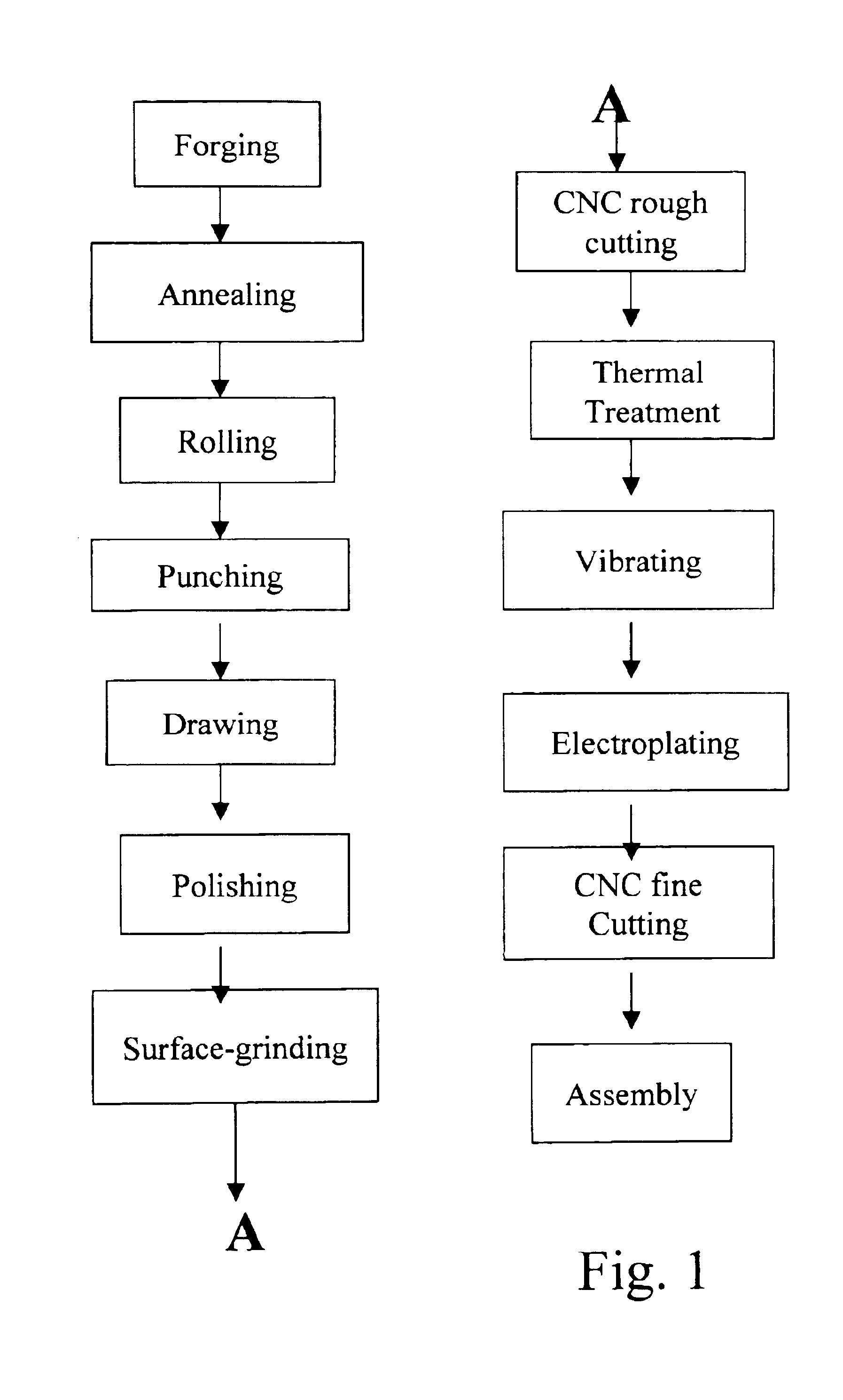
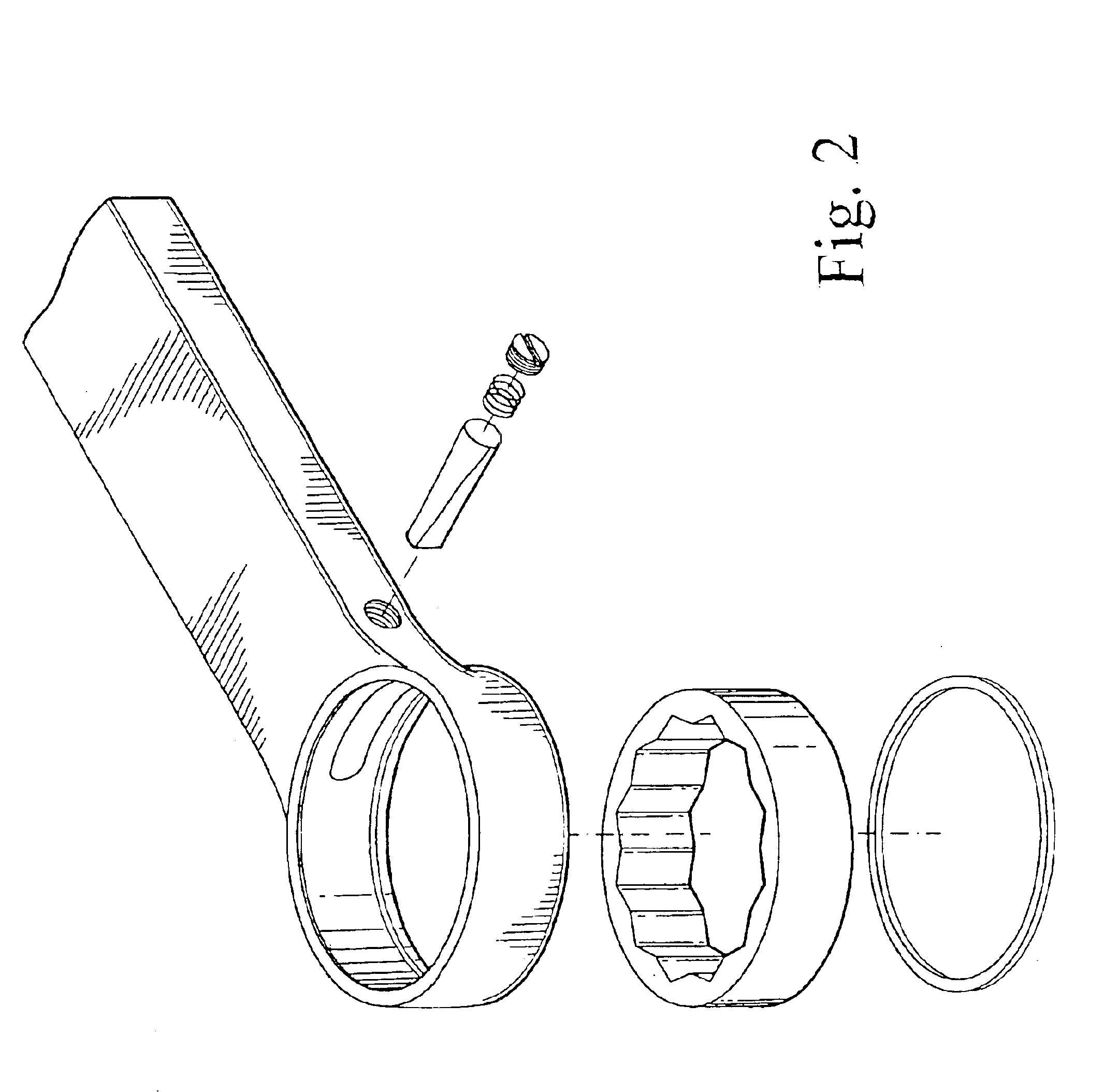
[0004]Accordingly, the primary objective of the present invention is to provide a wrench manufacturing process comprising the steps of: (a) forming a roughcast of a wrench by means of thermal forging; (b) annealing said roughcast of a wrench so as to soften the roughcast to facilitate subsequent processing; (c) performed a rolling process; namely to rub said roughcast of a wrench against sand granules in a rolling barrel, so as to remove carbide materials attached on said roughcast during said step of annealing; (d) shaping said roughcast of a wrench to a predetermined shape; (e) CNC rough cutting, whereby a receptacle space in a front section of said roughcast of a wrench is cut to attain a predetermined size; (f) cutting a receptacle space in a front section of said roughcast of a wrench to has a predetermined size by CNC rough cutting or MC cutting; (g) enhancing the structural toughness of said roughcast of a wrench by a heating process so that the structure is capable of resisting the stress caused by twisting a fixed object; (h) fining a surface of said roughcast of a wrench by chemical vibrations so that the roughcast is suitable for being electroplated; (i) coating said surface of said roughcast of a wrench with a protective layer to resist oxidation and attrition; (j) eliminating slight deformations due to said step of thermal treatment, of said receptacle space of said roughcast of a wrench by performing CNC cutting or MC fine cutting so that said receptacle space fits required degree of roundness, and an inner wall of said receptacle space is left with fine tool marks for providing a better frictional effect with a part set to be installed therein; and (k) coupling said roughcast of a wrench with said part set within said receptacle space thereof and being then locking said roughcast with said part set by a locking member.

Problems solved by technology

However, the conventional manufacturing process for an ordinary wrench is not suitable for wrenches of special purposes.
The conventional process can make a wrench identical in outlook to a unidirectional rolling-tube wrench, but the above requirements for confining a rotational tube cannot be attained.
Therefore, the wrench will be either easily deformed due to its lack of hardness, or have uneven stress around the receptacle space with the tube due to not being perfectly circular or be short of grasp force due to insufficient frictional coefficient.

Method used


Image

  • Wrench manufacturing process
  • Wrench manufacturing process
  • Wrench manufacturing process

Examples


Embodiment Construction

[0009]Referring to FIG. 1, a wrench manufacturing process according to the present invention comprises the steps of forging, annealing, rolling, external processing, CNC rough cutting, thermal treatment, vibrating, electroplating, CNC fine cutting and assembling. The step of external further includes punching, drawing, polishing and surface grinding. All the steps are specified as follows.[0010]1. In the step of forging, thermal forging forms the roughcast of a unidirectional rotational-tube wrench.[0011]2. In the step of annealing, the hardness of the roughcast is reduced to facilitate the subsequent processing.[0012]3. In the step of rolling, the roughcast rubs against sand granules in a rolling barrel, so that the carbide materials attached on the roughcast are removed.

[0013]The external processing comprises the following four steps.[0014]4. In the step of punching, the receptacle space of the roughcast is formed for that the workload of the subsequent cuttings is reduced.[0015]5...


PUM

PropertyMeasurementUnit
Sizeaaaaaaaaaa
Strengthaaaaaaaaaa
Toughnessaaaaaaaaaa

Abstract

A wrench manufacturing process for manufacturing a rotational-tube wrench comprises the steps of forging, annealing, rolling, punching, drawing, polishing, surface grinding, CNC rough cutting, thermal treatment, vibrating, electroplating, CNC fine cutting and assembling. The additional steps of thermal treatment and CNC or MC fine cutting not only enhance the structural toughness of the wrench but also guarantee high degree of roundness for the receptacle space thereof. The CNC or MC fine cutting also provides the inner wall of the receptacle space with fine tool marks so that the confinement strength of a rotational tube without ratchets therein can be significantly enlarged.

Description

FIELD OF THE INVENTION[0001]The present invention relates to wrench manufacturing processes, more particularly to a rolling wrench manufacturing process.DESCRIPTION OF THE PRIOR ART[0002]The wrench manufacturing processes of the prior art generally comprise the steps of (1) forging, (2) annealing, (3) rolling, (4) punching, (5) drawing, (6) polishing, (7) surface grinding, (8) vibrating and (9) assembling. The wrench initially takes shape in the step of forging. It then goes through the step of annealing so as to become softer for the subsequent cutting. The carbide materials attached on the wrench are taken off in a rolling barrel in the step of rolling. The wrench then goes through the steps of punching and drawing to take the final shape. The curved surfaces of the wrench are polished in the step of polishing, whereas the flat surfaces thereof arc processed in the step of surface grinding. Finally, the wrench goes through the step of vibrating in which it is fine processed and el...

Claims


Application Information

Patent Timeline
IPC IPC(8): B21K5/16B25B13/00B21K5/00B25B13/46B23P15/00
CPCB21K5/16B25B13/462B23P15/00
Inventor HSIEN, CHIN-CHING
Owner HSIEN CHIN CHING
Learn More