Vertebral stabilization assembly and method

a technology of vertebral stabilization and assembly, which is applied in the field of spinal stabilization, can solve the problems of increased surgical time, increased patient risk, and major muscle damage, and achieves the effects of reducing the total time required, and reducing the risk of major muscle damag

Inactive Publication Date: 2005-05-31
VAUGHAN MEDICAL TECH
View PDF42 Cites 175 Cited by
  • Summary
  • Abstract
  • Description
  • Claims
  • Application Information

AI Technical Summary

Benefits of technology

[0061]Yet another advantage of the present invention is that the engagement of the engaging portion of the shaft of the pedicle screw with the connecting screw prevents the pedicle screw or the connecting screw from moving or backing out of the vertebra since the connecting screw and pedicle screw are connected to one another.
[0062]Another advantage to the present invention is that the added stability of the pedicle screw posteriorly placed and connected to the connecting screw anteriorly insures for maximum stabilization and attachment of the connecting member and thus greater vertebral stabilization. Another advantage to the present invention is that the pedicle screw may be percutaneously placed by making only a small posterior incision and thus overcoming the disadvantages associated with posterior fusion requiring large posterior muscle dissection and the problems associated therewith. For this reason, the present invention is safer for the patient.
[0063]Anterior stabilization via connection to posteriorly placed pedicle screws has numerous advantages including significantly reducing the total time required for the surgical procedure. Avoidance of the radical muscle dissection required for posterior connection and stabilization is one factor in reducing the time to perform the surgery to about 2.5 hours versus the 5 to 7 hours such a procedures ordinarily requires. Thus, anterior stabilization via connection to posteriorly placed pedicle screws provides numerous advantages over prior vertebral stabilization systems and methods.
[0064]As well as being placed percutaneously, the pedicle screw may be positioned so that a head of the pedicle screw is substantially flush with the surface bone of the vertebra. Such placement further reduces interference with back muscles and associated problems and presents another advantage according to one aspect of the present invention.
[0065]Another advantage is that the present invention allows for the drill bit to be disposed within the cannulated portion of the shaft of the pedicle screw for only minor penetration of the surface of the anterior side of the vertebra to avoid the risk of damage to soft tissue adjacent the anterior of the vertebra.
[0066]Another advantage of the present invention is that the guide member allows for alignment of the connecting screw with the engaging portion of the pedicle screw without the necessity for time-consuming and inaccurate x-rays, MRI's, or other similar scanning or locating devices.

Problems solved by technology

Spinal problems may be caused by a trauma to the spine received during an accident, excessive strain or stress on the spine from physical activities, a sedentary lifestyle and poor posture that may place abnormal pressure on the spine, disease or a variety of other reasons.
However, posterior fusion requires large posterior muscle dissection to safely implant the pedicle screws and provide for placement of the plate.
Such major muscle damage presents a danger to the patient during surgery from infection and the extensive muscle damage.
Also, additional time is required to perform both extensive anterior and posterior surgical portions.
The added surgical time presents another risk to the patient.
Although anterior fusion avoids the problems associated with the larger posterior fusion, additional problems arise.
Lateral placement requires a significantly more invasive procedure and much greater exposure.
Also, screws anchored laterally through the anterior of the vertebra do not provide the stability of those extending posteriorly through the pedicle and into the vertebral body.
Furthermore, anteriorly-anchored screws do not promote quick and uniform fusion of the bone graft to the vertebra since they do not have the stability of the pedicle fixation.

Method used


Image

  • Vertebral stabilization assembly and method
  • Vertebral stabilization assembly and method
  • Vertebral stabilization assembly and method

Examples


Embodiment Construction

[0104]It should be understood at the outset that although an exemplary implementation of the present invention is illustrated below, the present invention may be implemented using any number of techniques, whether currently known or in existence. The present invention should in no way be limited to the exemplary implementations, drawings, and techniques illustrated below, including the exemplary design and implementation illustrated and described herein.

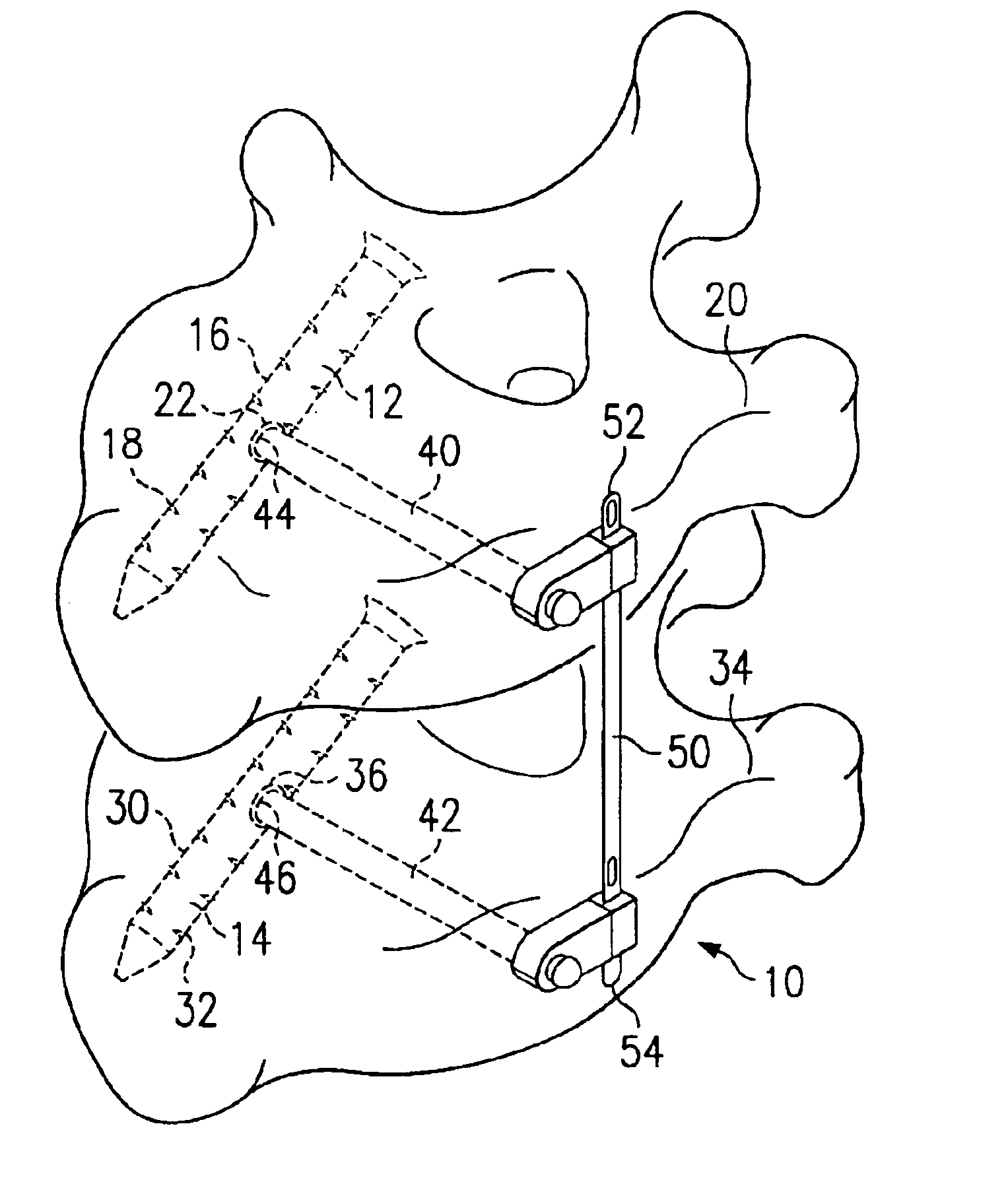
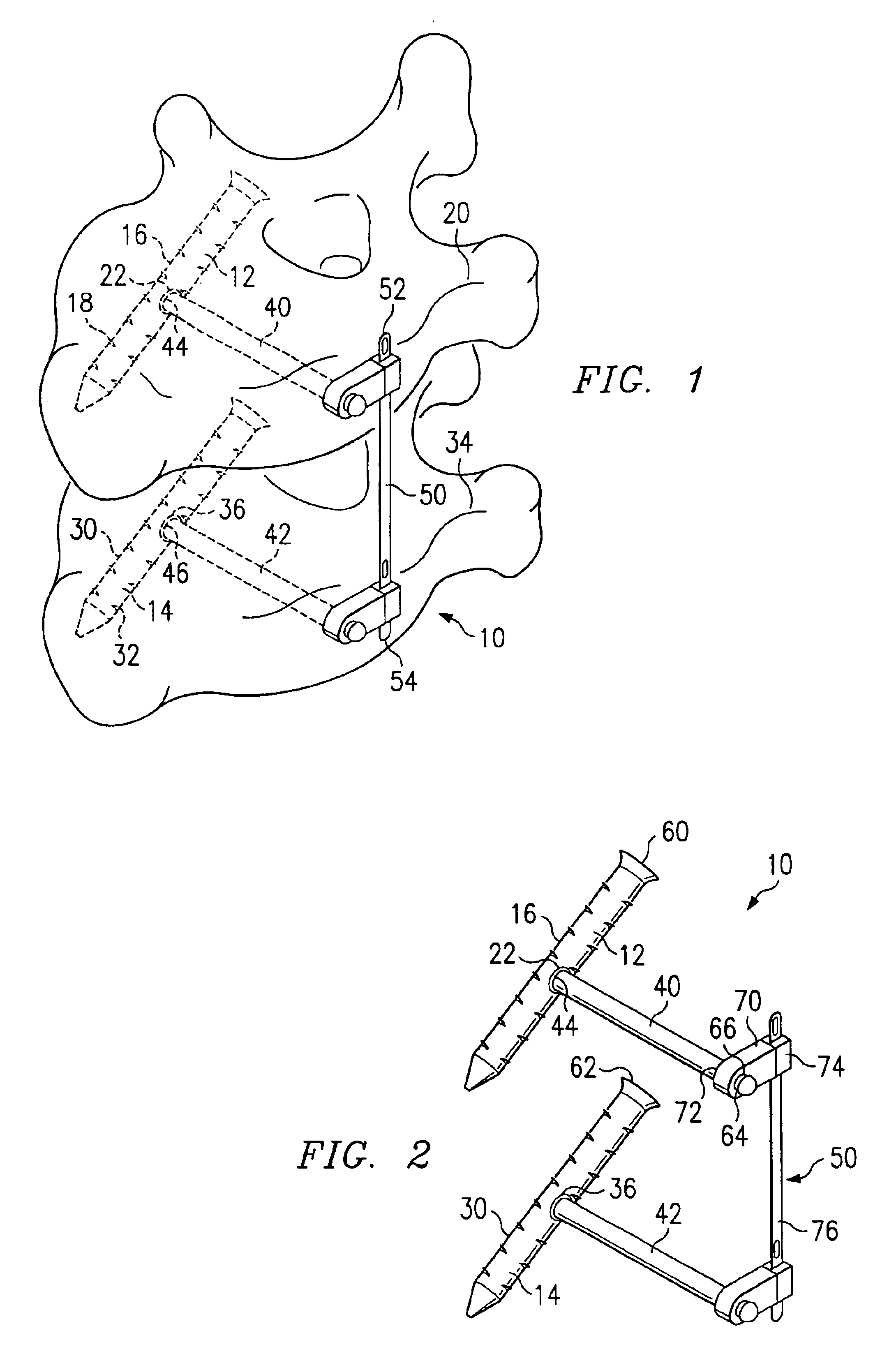
[0105]FIG. 1 illustrates one aspect of the vertebral stabilization assembly 10 constructed in accordance with the present invention. The vertebral stabilization assembly 10 is an innovative device for stabilizing a plurality of vertebrae of the spine. The vertebral stabilization assembly 10 includes a first pedicle screw 12 and a second pedicle screw 14. The first pedicle screw includes a shaft 16 provided with a threaded portion 18. The threaded portion 18 of the shaft 16 is operable for threading engagement of the first pedicle scr...


PUM


Abstract

A vertebral stabilization assembly for stabilizing vertebrae is provided. The vertebral stabilization assembly includes a first and a second pedicle screw, a first and second connecting screw, and a connecting member. The first and second pedicle screws each have a shaft provided with a threaded portion operable for threading engagement of the first and second pedicle screws with a first and second vertebra, respectively, each shaft also has an engaging portion. The first and second connecting screws each have a first end adapted to be received by the engaging portions of the first and second pedicle screws, respectively. The connecting member has a first end connected to the first connecting screw and a second end connected to the second connecting screw for stabilization of the first and second vertebra. A guide member for placement of the connecting screw and method for anteriorly stabilizing vertebrae is also provided.

Description

CROSS-REFERENCE TO RELATED APPLICATIONS[0001]Pursuant to 35 U.S.C. §119(e), this application claims the benefit of U.S. Provisional Patent Application No. 60 / 327,118, entitled Vertebral Stabilization Assembly and Method, filed Oct. 3, 2001, and U.S. Provisional Patent Application No. 60 / 350,259, entitled Vertebral Stabilization Assembly and Method Having a Modified Pedicle Screw, filed Nov. 2, 2001, and U.S. Provisional Patent Application No. 60 / 331,857 entitled Vertebral Stabilization Assembly and Method for Anterior Placement, filed Nov. 20, 2001, and U.S. Provisional Patent Application No. 60 / 353,691, entitled Vertebral Stabilization Assembly and Method Having Dual Pedicle Screws, filed Jan. 31, 2002, all naming Paul A. Vaughan as inventor, which are hereby incorporated by reference for all purposes.TECHNICAL FIELD OF THE INVENTION[0002]The present invention relates generally to a spinal stabilization and more specifically, but not by way of limitation, to a vertebral stabilizati...

Claims


Application Information

Patent Timeline
Patent Type & Authority Patents(United States)
IPC IPC(8): A61B17/17A61B17/16A61B17/70A61B17/88A61B19/00A61BA61B17/56A61B17/58
CPCA61B17/1757A61B17/70A61B17/7082A61B17/1735A61B17/7001A61B2017/8655A61B17/8875A61B19/52A61B17/7059A61B90/36
Inventor VAUGHAN, PAUL A.
Owner VAUGHAN MEDICAL TECH
Why Eureka
Try Eureka