High-toughness wear-resistant steel

a technology of wear-resistant steel and high-toughness, which is applied in the field of high-toughness wear-resistant steel, can solve the problems of increasing the work environment of these machines, increasing the cost of the technique disclosed in japanese patent kokai publication gazette no. 5, 78781, etc., and achieves the effect of improving toughness, preventing the strength of the grain boundary from decreasing, and improving toughness

Inactive Publication Date: 2005-05-31
KOMATSU LTD
View PDF3 Cites 21 Cited by
  • Summary
  • Abstract
  • Description
  • Claims
  • Application Information

AI Technical Summary

Benefits of technology

[0009](1) Reinforcement of the grain boundary is made to be possible by combined addition of Al and Ni, thereby achieving dramatically improved toughness.
[0051]Like P, S is an element which is liable to surface segregation as well as grain boundary segregation and causes a decrease in the strength of the grain boundary. According to the invention, the amount of Mn which actively produces sulfide is controlled such that the ratio of S to M (wt %) of the steel is made to be 0.01 or less to allow the precipitation of Mns, thereby reducing the solid concentration of S in the steel matrix and reducing the grain boundary segregation to prevent a decrease in the strength of the grain boundary.

Problems solved by technology

However, there have been strong demands to harder and tougher wear-resistant steel in view of cost reduction and the work environment for these machines which is getting severer in recent years.
The technique disclosed in Japanese Patent Kokai Publication Gazette No. 5-78781 tends to be costly, because the contents of P, S and Mn are reduced while expensive Mo is used in a large amount.
In addition, this publication has revealed the disadvantage in its embodiment that toughness is obtained provided that high-temperature tempering up to secondary hardening temperature is carried out, so that hardness is not high enough and wear resistance is unsatisfactory.

Method used


Image

  • High-toughness wear-resistant steel
  • High-toughness wear-resistant steel
  • High-toughness wear-resistant steel

Examples


first embodiment

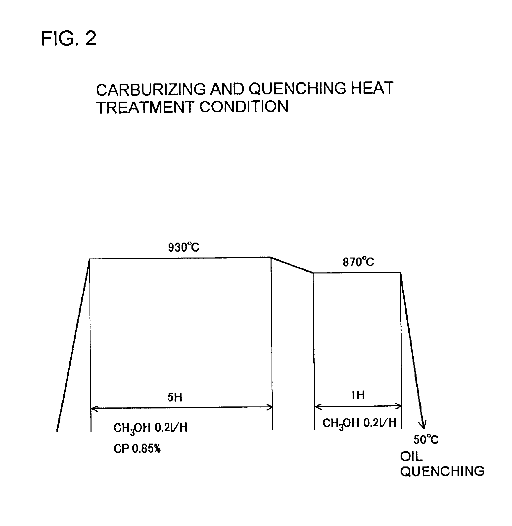
[0058]( Carburizing TP Test)

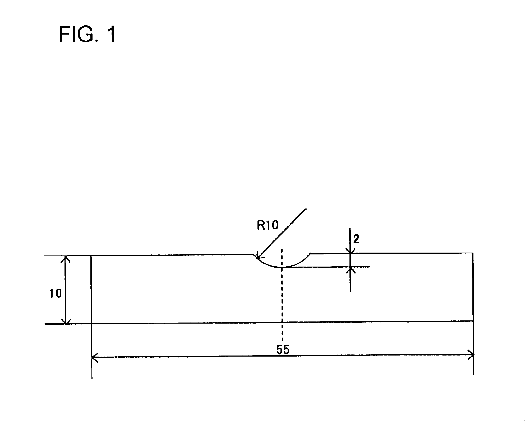
[0059]The steel compositions employed in this embodiment are shown in Table 1. Ingot steel was produced from each material in a high frequency melting furnace having a weight of 25 kg and shaped into a 35 mm diameter round bar by hot forging. Then, the rod was subjected to normalizing at 980° C. and machined to make a Charpy impact test specimen of the shape shown in FIG. 1.

[0060]

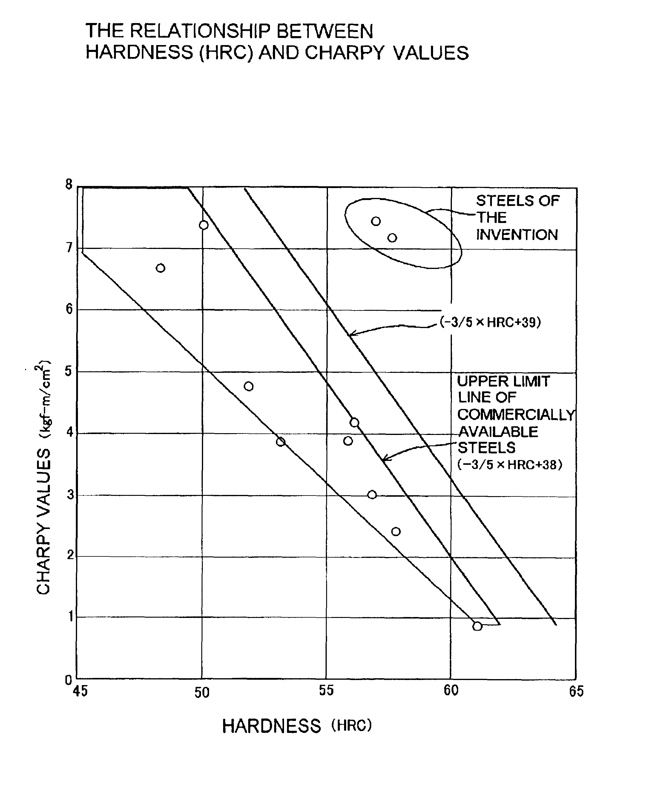
TABLE 1Steel material compositions and the results of Charpy impact testssurfaceCharpyS / MnNoCSiMnNiCrMoVPSAlBTihardnessvaluesratioA0.20.070.51.010.260.0060.0031.070.00162.52.50.006*B0.190.071.1911.010.250.0050.0051.060.008627.60.004C0.220.220.821.150.150.0070.0050.033631.90.006*D0.210.071.1911.010.250.0130.011.06625.90.008*E0.210.070.891.021.010.250.0050.0060.2962.54.60.007*F0.220.081.160.490.520.230.0060.0050.73624.90.004*G0.20.230.78 2.110.950.150.0150.0141.5361.55.70.018H0.210.230.761.970.920.160.0160.0120.03561.52.60.016I0.190.211.150.010.020.0130.0150.02962.51.30.013*J0.20.2...


PUM

PropertyMeasurementUnit
temperatureaaaaaaaaaa
weightaaaaaaaaaa
temperatureaaaaaaaaaa

Abstract

A primary purpose is to provide an inexpensive high-toughness wear-resistant steel having satisfactory toughness where its hardness is HRC 55 or more. This steel contains at least 0.21 to 0.80 wt % C; 0.3 to 2.0 wt % Al; and 0.5 to 4.0 wt % Ni as essential components and further contains alloy elements such as Si, Mn, Cr, Mo, W, V, Ti, Cu and B; unavoidable impurities such as P, S, N and O; and the remainder which substantially consists of a tempered martensitic steel of Fe.

Description

TECHNICAL FIELD[0001]The present invention relates to high-toughness wear-resistant steel having high hardness as well as excellent toughness and applicable to excavating teeth for construction equipment (e.g., excavators and bulldozers) and to crawler belt links, rollers, bushings and sprockets for track-type vehicles. More particularly, the invention relates to high-toughness wear-resistant steel composed of tempered martensitic steel to which Al and Ni has been added in combination.BACKGROUND ART[0002]Examples of excavating teeth for use in construction equipment include ripper points, bucket teeth and cutting edges which work in rock and excavate the ground. Many parts such as crawler belt links, rollers, bushings and sprockets for track-type vehicles require high impact resistance and high wear resistance which are generally known to be inconsistent with each other.[0003]As such wear-resistant steel, there have been widely used SNCM, SCrB and SMnB-base medium carbon steels whic...

Claims


Application Information

Patent Timeline
Patent Type & Authority Patents(United States)
IPC IPC(8): C22C38/06C22C38/58C22C38/00C22C38/08
CPCC21D9/22C22C38/02C22C38/04C22C38/48C22C38/22C22C38/24C22C38/44C22C38/46C22C38/06C21D6/001C21D2211/008
Inventor TAKAYAMA, TAKEMORINAKAO, CHIKARA
Owner KOMATSU LTD
Why Eureka
Try Eureka