
Aircraft electrostatic discharge test system

Inactive Publication Date: 2005-05-31
BAE SYST INFORMATION & ELECTRONICS SYST INTERGRATION INC
View PDF44 Cites 22 Cited by
  • Summary
  • Abstract
  • Description
  • Claims
  • Application Information

AI Technical Summary

Benefits of technology

[0034]In addition, the present invention's use of at least two E-field sensors in conjunction with a means of coherent signal processing enables substantial reduction of background noise. This, in turn, permits detection of E-field distortion at greater ranges and facilitates signature correlation of the detected object with characteristic E-field distortions of like and similar sources.
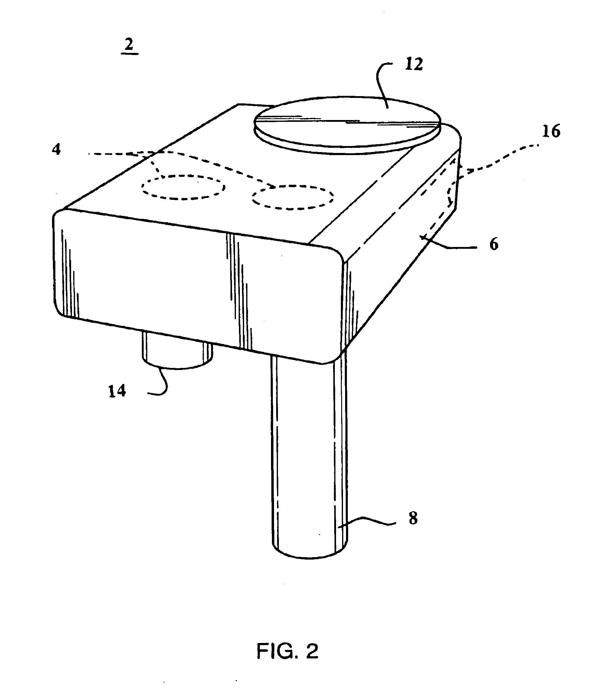
[0036]One embodiment of the present invention is a detection system comprising an array of inexpensive, miniaturized sensors that are easily deployable and are in communication with a means of processing and outputting the detected E-field disturbance indications for interpretive display and analysis. It is anticipated that the relative simplicity of the sensor devices and their low power requirement of 1-2 milliwatts enables persons of ordinary skill in the art to augment or supplant battery power sources with, for example, solar, piezo electric, and inductive power sources for some embodiments. Similarly, other devices such as GPS receivers, low-power transmitters and data links, repeaters, and triggers can be incorporated into embodiments of the present invention to improve its usefulness in particular applications.

Problems solved by technology

Measurements outside a given range indicate that the ESD system of the aircraft is not working properly.
E-field distortions are caused by the spatial imbalance of ions, wherein such distortions are caused by the movement of charged bodies disrupting the electric fields.
And, E-fields are also generated by planes and other aircraft as they move through the air and cause E-field disruptions.

Method used


Image

  • Aircraft electrostatic discharge test system
  • Aircraft electrostatic discharge test system
  • Aircraft electrostatic discharge test system

Examples


Embodiment Construction

[0059]To those skilled in the art, the invention admits of many variations. The following is a description of a preferred embodiment, offered as illustrative of the invention but not restrictive of the scope of the invention. E-field sensors and systems according to the present invention exploit unintended and unavoidable electrostatic emissions in the spectrum from sub 1 Hz to greater than 1 MHz. Testing of the sensors in 2002 at a moderate use airport revealed a static dissipation problem with approximately 10% of incoming aircraft among the major airlines.

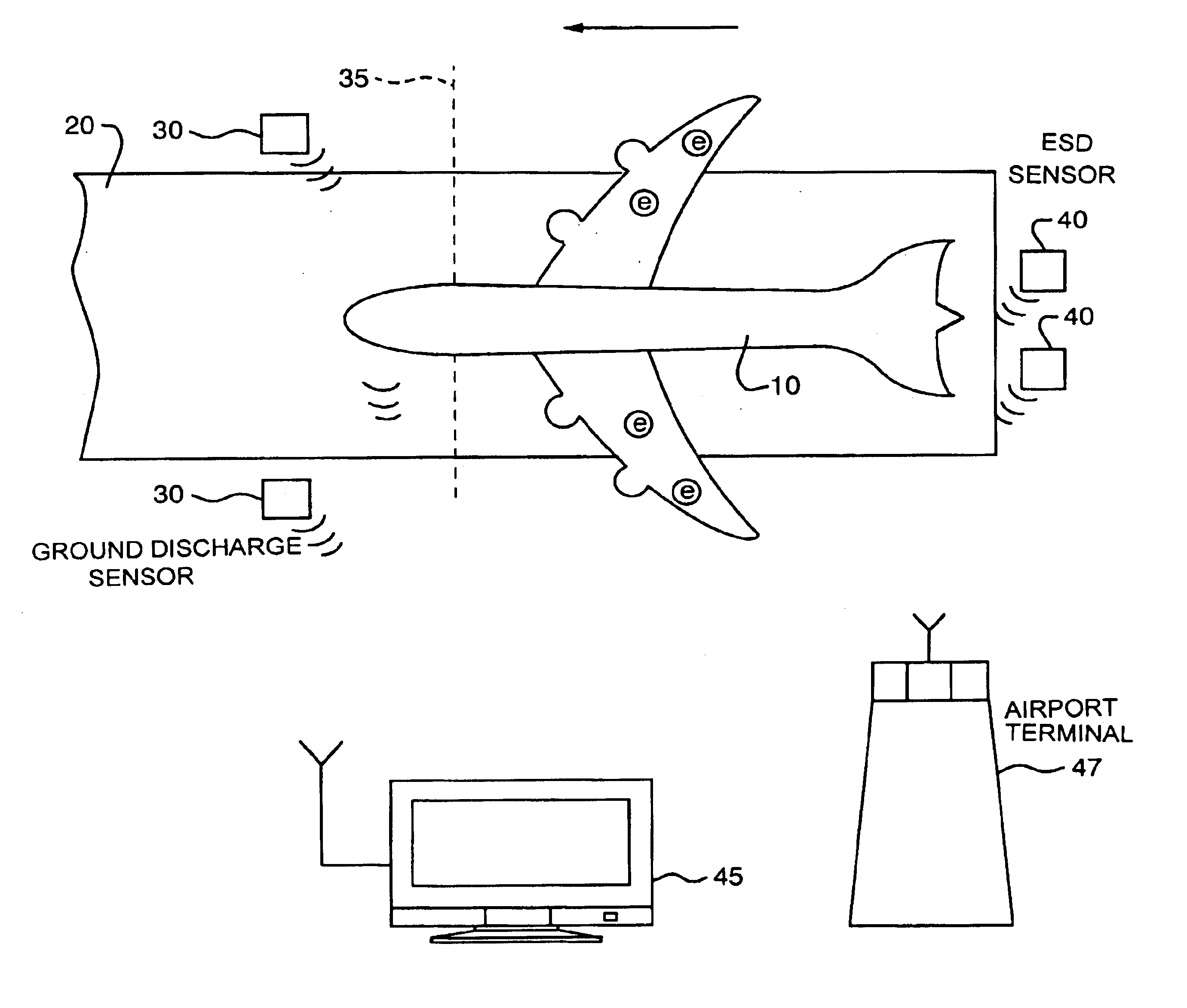
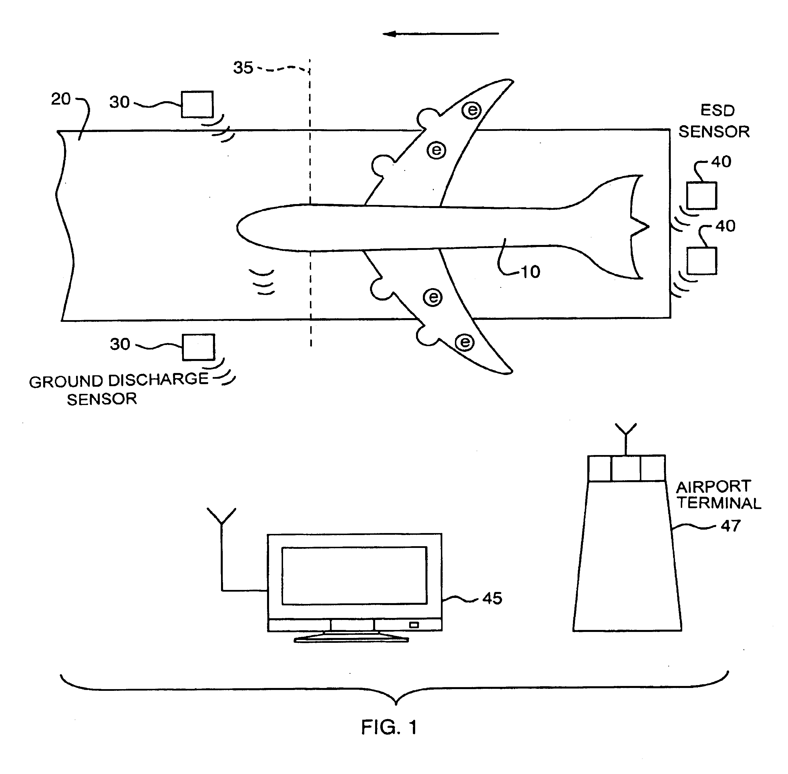
[0060]As shown in FIG. 1, the present invention allows passive testing of airborne aircraft ESD systems that are supposed to eradicate electrostatic charge ‘e’ from building up on the surface skin of the plane 10. As an airplane 10 is landing on the runway 20, one ore more airborne testing sensor devices 40 are located in close proximity to the runway 20 prior to touchdown. The sensors 40 should be placed with an unobstructed vi...


PUM


Abstract

A low cost diagnostic system for testing the airborne static discharge systems and the grounding systems for aircraft. The present invention is a passive electrostatic detection scheme which in one embodiment is an array of inexpensive, miniaturized sensors for measuring the detected E-field disturbances from aircraft. The measurements are taken on the runway upon arrival and indicate whether the aircraft had an appreciable accumulated charge indicating a failure of the electrostatic discharge system. The system further verifies that the ground discharge devices are properly working and any charge is dissipated upon landing. In one embodiment the measurement information is transmitted to a central location where the aircraft and the measurement data are matched and maintenance is scheduled for aircraft having high levels of electrostatic charge.

Description

CROSS REFERENCE TO RELATED APPLICATIONS[0001]This application claims priority under 35 USC 119(e) to U.S. Provisional Patent Application No. 60 / 325,878 entitled AIRCRAFT ELECTROSTATIC DISCHARGE TEST SYSTEM, filed on Sep. 28, 2001 and U.S. Provisional Patent Application No. 60 / 340,176 entitled ELECTRIC FIELD SENSOR filed Dec. 10, 2001.BACKGROUND OF THE INVENTION[0002]1. Technical Field of the Invention[0003]This invention relates to an apparatus and method for passive testing of the electrostatic discharge systems (ESD) installed on all types of aircraft.[0004]2. Background of the Invention[0005]Air travel and cargo transport has been steadily increasing over the last few decades, resulting in increased number of flights and flight locations. The flights require around the clock transportation of persons and cargo and in all types of weather. With the increasing number of planes in the air at a given time, there is a growing need to keep planes in the air for longer periods and with ...

Claims


Application Information

Patent Timeline
IPC IPC(8): G01D9/00G01R31/00
CPCG01D9/005G01R31/005G01R31/001
Inventor ZANK, PAUL A.SUTPHIN, ELDON M.BUCHANAN, DAVID W.CEHELNIK, THOMAS G.
Owner BAE SYST INFORMATION & ELECTRONICS SYST INTERGRATION INC
Learn More