

Magnetic switch capable of instantaneous switching of an output signal and magnetic sensor
- Summary
- Abstract
- Description
- Claims
- Application Information
AI Technical Summary
Benefits of technology
Problems solved by technology
Method used
Image

Examples
Embodiment Construction
[0029]Embodiments of the present invention will be hereinafter described with reference to the accompanying drawings.
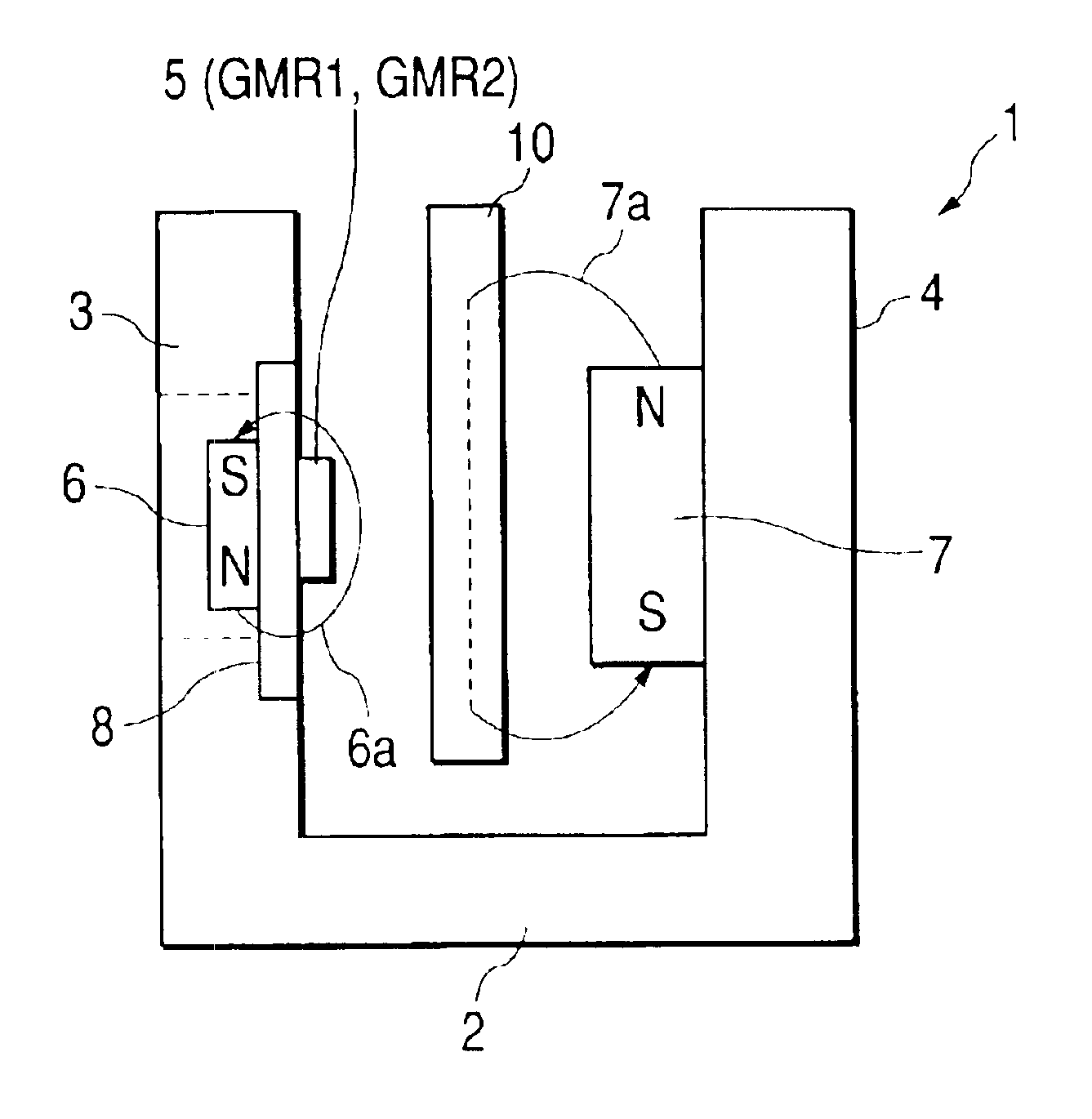
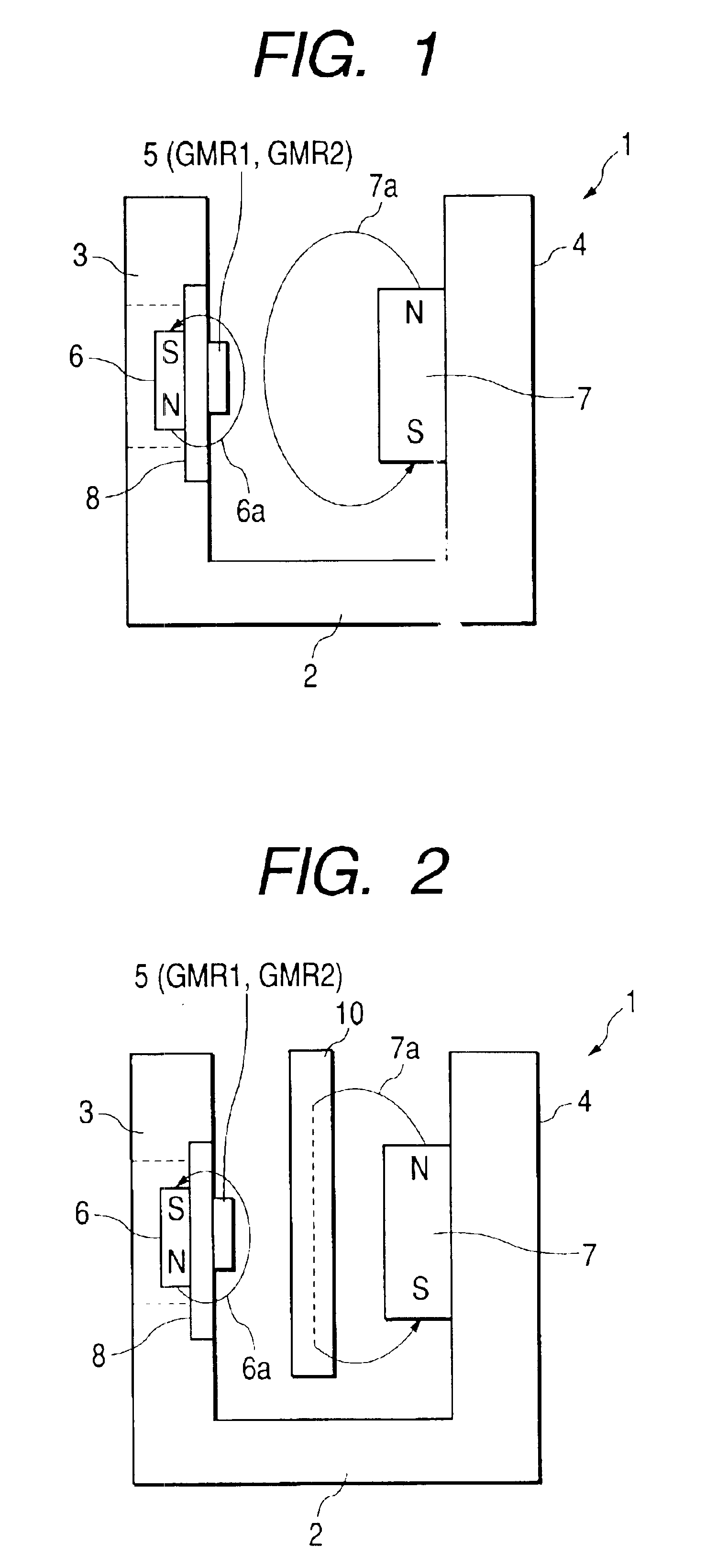
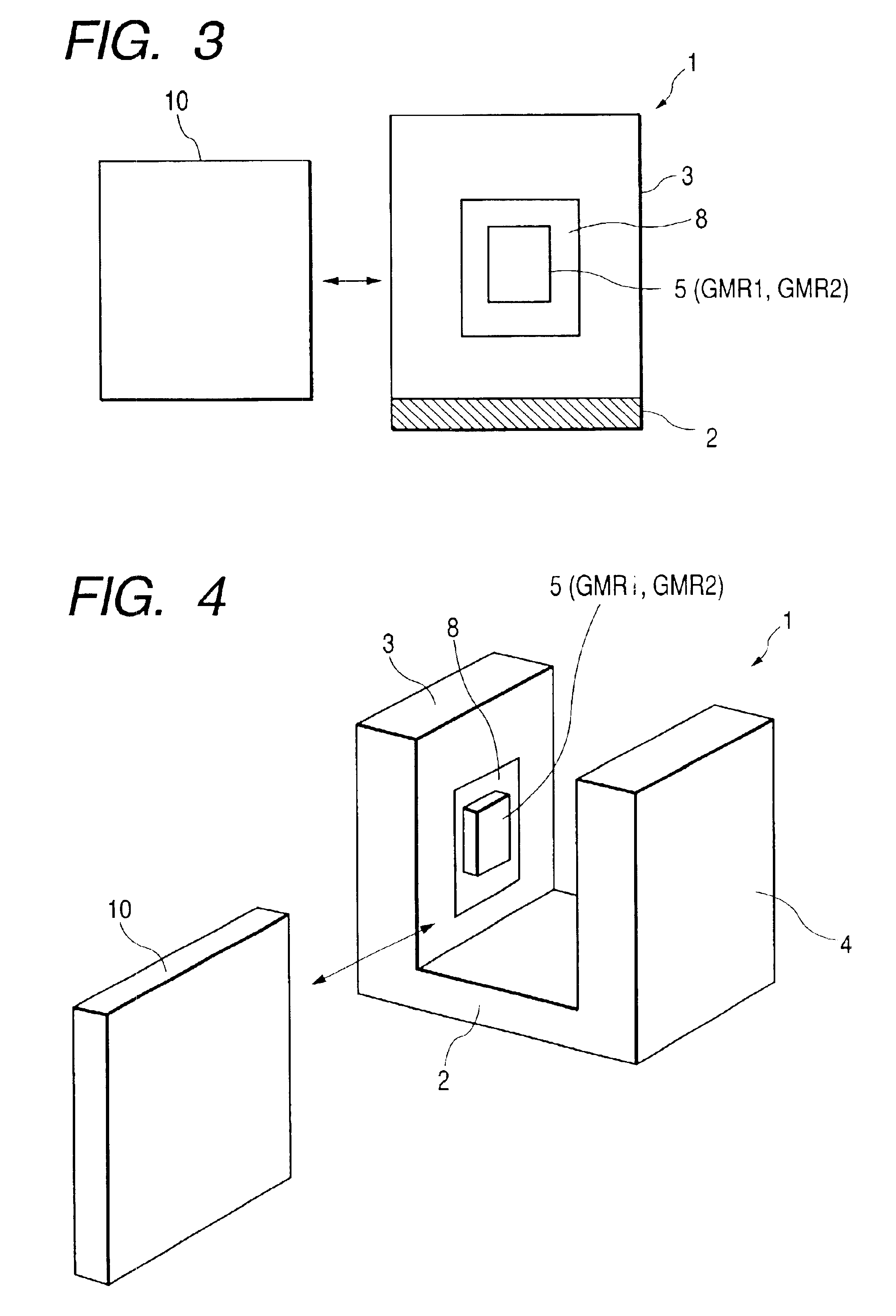
[0030]As shown in FIGS. 1, 2, and 4, a holder 1 of a magnetic switch has an inverted gate shape in which a pair of arms 3 and 4 are provided at both ends of a base 2 so as to extend parallel with and be opposed to each other. The one arm 3 is provided with magnetoresistive elements 5 and a second permanent magnet (hereinafter referred to as “second magnet”) 6, and the other arm 4 is provided with a first permanent magnet (hereinafter referred to as “first magnet”) 7.
[0031]The magnetoresistive elements 5 are provided in a hermetic structure by using an IC package or resin sealing and mounted on a board 8. And the magnetoresistive elements 5 are attached to the inner surface of the arm 3 via the board 8.
[0032]The second magnet 6 is attached to the arm 3 at a magnetic field acting position where to magnetize free layers 5d (see FIG. 5) of the magnetoresistive elements 5....
PUM
 Abstract
Description
Claims
Application Information